Jailbars - a new approach.
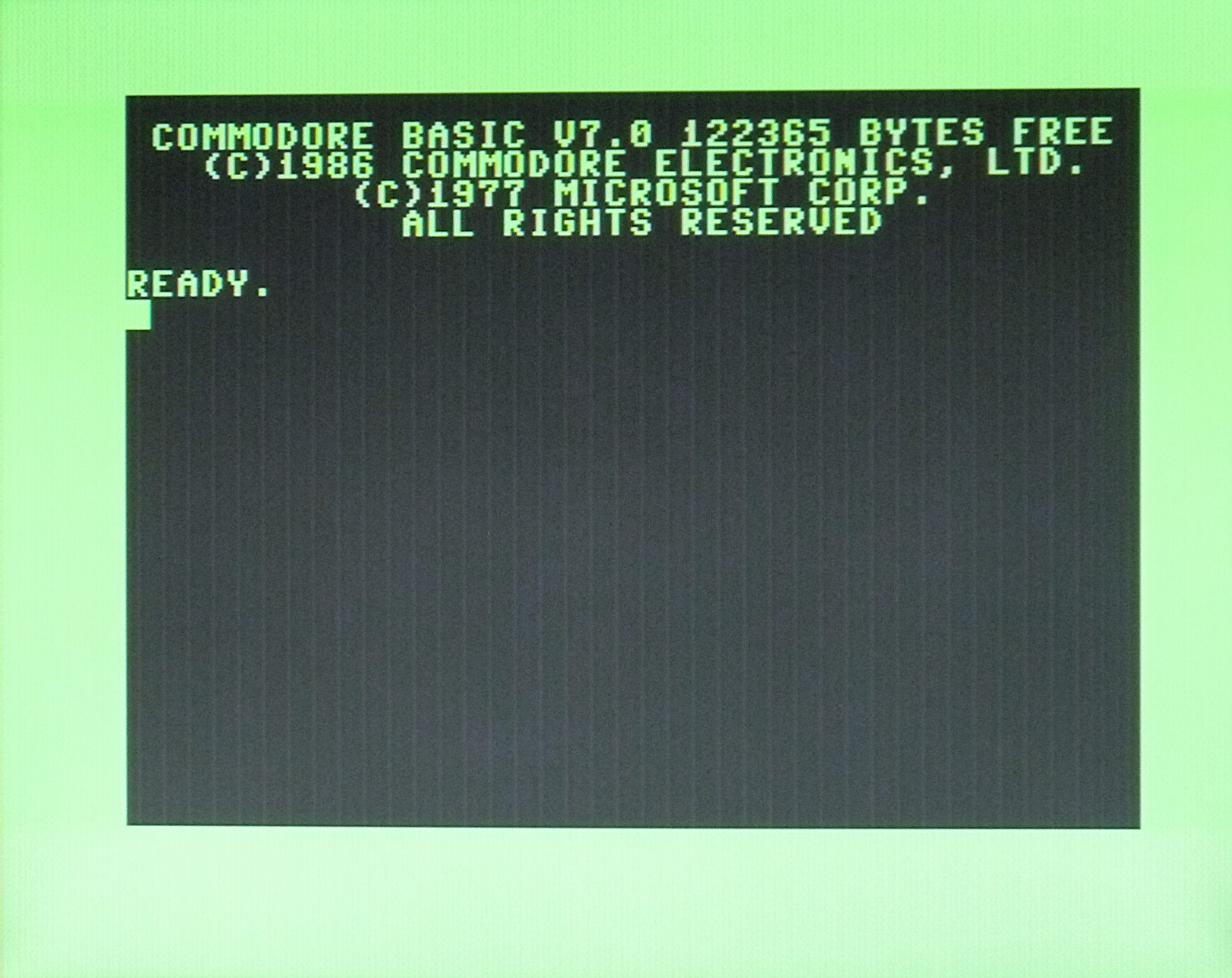
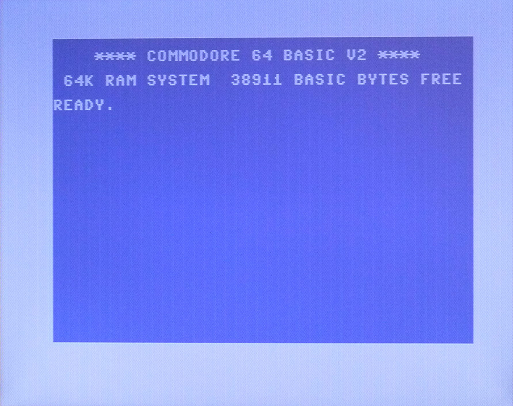
Commodore computers like the C-64 and the C128 always had spurious vertical bands in their video displays. These were commonly called "Jailbars". They were sometimes rather annoying, especially if you have a good quality S-video monitor, which does a good job of making those bars look sharper and more obvious. The C128 was especially notorious for having very visible jailbars. In the screenshots below you can see how they look on a C128 (left) and a C128 in C64 mode (right). These were taken from an LCD monitor, CRT users have said that the bars can look even worse than shown here.
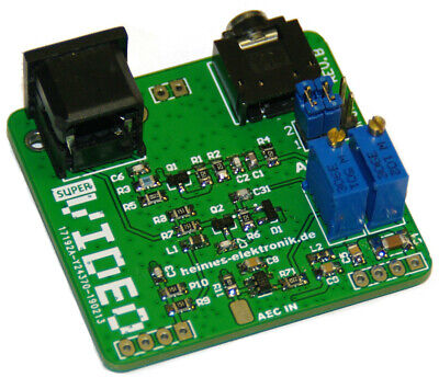
It is possible to minimise these bars by using a small PCB assembly that plugs into the VIC chip socket, with the VIC chip being plugged into this PCB. This device takes one or more of the most offending clock signals, inverts them, and then superimposes them onto the video signal by an amount controlled by the user, hopefully cancelling out the jailbars. Examples of these are the "LumaFix64 for the C-64 and the "LumaFix128" for the C-128. There is also a replacement RF modulator that also has this feature, called the "Super Video". These are normally only compatible with the machines they are designed for, though of course, a C128 version will also work when the C-128 is in C-64 mode. Results from these adaptors can sometimes be a bit patchy, often caused by the wide variety of motherboard and chip revisions Commodore went through over the years. These variations meant that the crosstalk had different effects in different versions, making it hard to make an effective solution for all cases.
Below, a SuperVideo RF modulator replacement showing the AEC input pad.
What causes jailbars?
Jailbars are mainly caused by crosstalk between various clock signals used by the computer leaking into the video signal. Other causes could be poor bypassing or filtering of the power supply used by the video circuitry. Usually, these bars are very fine vertical lines, the spacing of which is determined by the frequency of the offending clock signal. The examples above are consistent with a frequency of about 1MHz, which is the most common clock frequency in a C-64 or C-128. Higher clock frequencies will cause the lines to be closer together. The fact that the jailbars are usually in the form of thin lines rather than alternating light/dark bands indicates that the problem is likely caused by stray capacitance between the video circuitry and the various clock circuits in the machine. These stray capacitances can vary from machine to machine and even more so when comparing machines with different versions of PCBs that have different layouts. Different versions of the VICII chip can also play a part. This means that a solution that may work best on one machine may not be as effective on another.
It is worth pointing out that jailbars can also occur in the chrominance (C) channel in machines using the separate luma/chroma (S-Video) connections. To my knowledge, none of the 'Lumafix' boards correct this. I experimented with trying to modify and shield the chrominance channel too, but got no improvement. Fortunately in most cases chrominance jailbars are usually almost invisible, except for the VIC-20 and the "long board" C64s and the non DCR version of the C128.
Naughty Commodore!
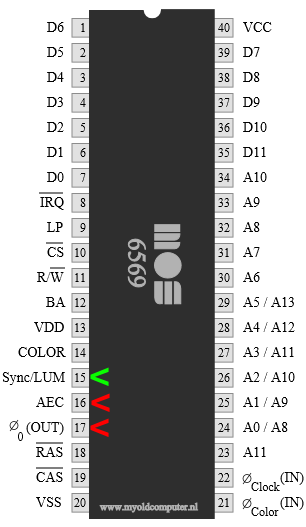
A lot of this crosstalk is caused by bad chip design and PCB layout. In the VICII chip used in the C-64, Commodore chose to put the AEC clock signal on pin 16, right next to the luminance (video) out pin at pin 15! You couldn't choose a worse pin location if you tried! Poor PCB layout (in the early "long" board C-64s) only added to the problem. In the later "short" board C-64s, Commodore realised their mistake and improved the layout somewhat, though there are limits to what you can do with a two layer board, and a bad chip pinout. From my experience, the later short board C-64s do tend to be a bit better in that they can show less jailbars, and the LumaFix adaptors tend to be much more effective. Below is the pinout for a 6569 VICII chip for the C-64. You can see that two clock signals are very close to the luminance out pin, AEC and PH0. Note that I'll be referring to the PAL versions of the various VIC-II chips here, but everything should also apply equally to the NTSC versions.
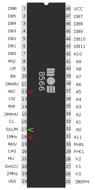
At first glance, it appears that Commodore learnt that lesson for the 8566 VIC chip for the C-128. Luminance out was now pin 17, and AEC was now pin 12. Plenty of distance from each other. Unfortunately they moved the 1MHz system clock to pin 18, so we still have the problem of a strong 1MHz clock signal right next to the video signal.
An alternative approach.
Currently, the approach used to mitigate jailbars is to try to cancel them out. Wouldn't it be better if we tried to stop or reduce them from happening in the first place? While we don't have much control over crosstalk from the clock pins being right next to the luminance pin, we can re route or shield the connection from the luminance out pin to its destination - the RF modulator, and then eventually the video output socket. If carefully done, this would eliminate crosstalk coming from this source.
Another possibility is to modify the offending clock signal to make it less prone to causing crosstalk. Normally the clock signal is a square wave with fairly fast rise and fall times. It is the fast transitions from low and high states that get capacitively coupled into the video signal, causing the jailbar lines. If the clock signal could be modified to slow these transitions, the coupling will be reduced, reducing the lines. Of course, one could only go so far with this, as interfering with the clock signal too much could cause all kinds of problems with the computer. In many cases ferrite beads are already used in the clock and video lines to try to achieve this, but they never seem to work well enough.
Originally, I intended to make this all one webpage, but I very soon found myself down a deep rabbit hole with all the complexities and permutations of the various Commodore models and methods of jailbar removal. I decided it was simpler to break it up into the techniques needed for the various models as listed below. Unfortunately I don't have any experiences of other Commodore models not listed below.
S-video modification and jailbar removal for the VIC-20
S-video modification and jailbar removal for the VIC-20CR
Jailbar removal for the C-64 (long board)
Jailbar removal for the C-64C
Jailbar removal for the C-128
Jailbar removal for the C-128DCR
Back to main Amiga page.
Introduced 29th June 2023. Version 1.0