Jailbars - a new approach.
S-video and jailbar removal for the VIC-20CR
While somewhat improved compared to the earlier "long board" version of the VIC-20, the display quality was still terrible. The VIC-20CR was sold at a time when very few TVs had composite video input, so users had to use the provided external RF modulator. Luckily the VIC 20 had a very low resolution screen with large characters so the poor quality wasn't a total showstopper. For those lucky enough to be able to use the composite video output, the quality was still rather dire. While the 6561 VIC chip (6560 for NTSC) had separate luminance and chrominance output (S-Video), the VIC-20 did not support this as the two signals were combined to make a standard composite output. Commodore seemed to have fiddled with the video output design quite a bit. I have seen three different revisions on three different circuit schematics, and the machine I have is different again. Surprisingly, my machine has a pretty good display apart from the smearing and softness. Others I have seen over the years are usually far worse. One thing that is a little surprising is that Commodore didin't make the mistake of placing the luminance pin next to a clock pin on the 6561 chip, unlike their later designs, so there was not a serious problem with jailbars in the luminace signal. The 6561 chip does, however, suffer from a 1MHz clock signal getting into the chrominance (colour) signal. Fortunately there are ways to mitigate this as will be shown later.
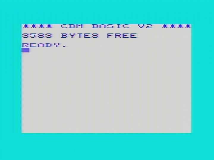
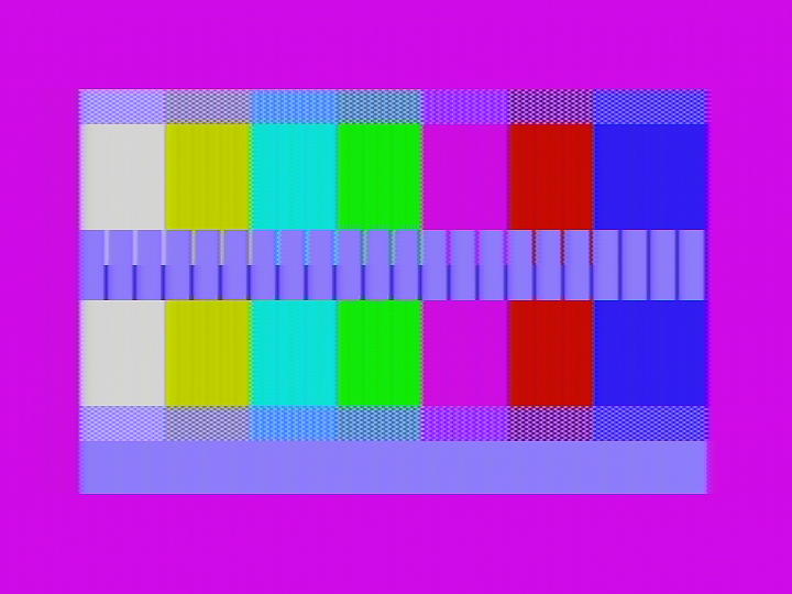
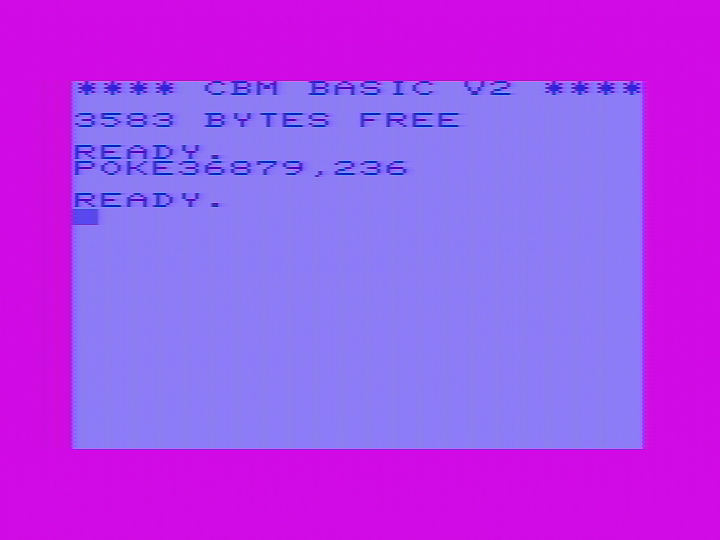
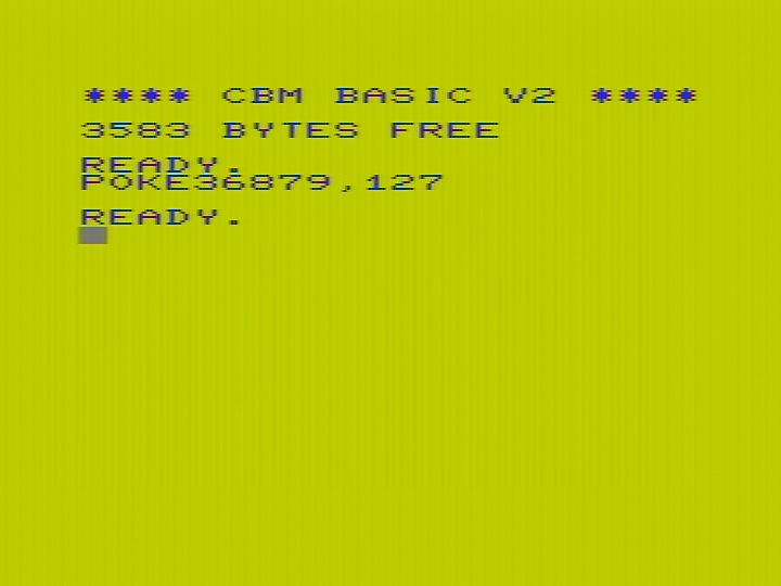
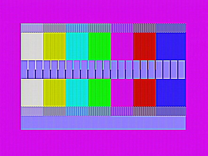
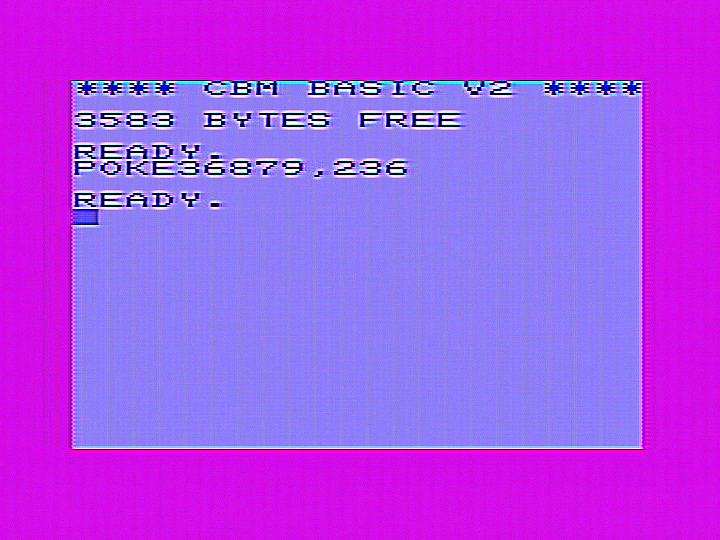
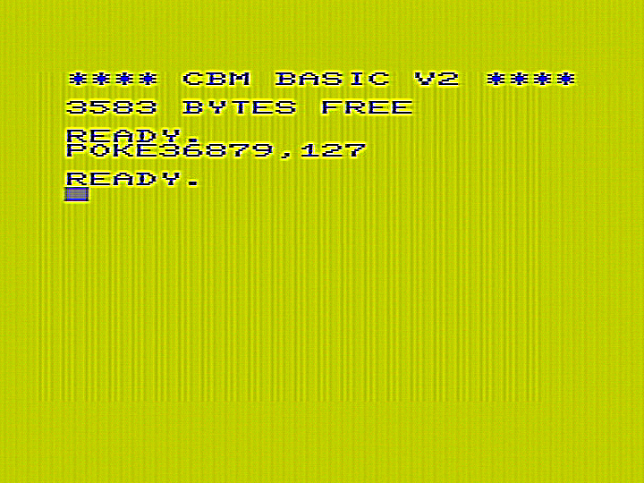
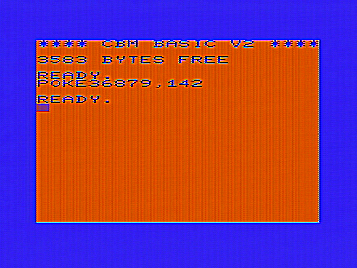
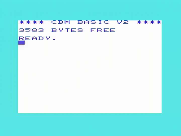
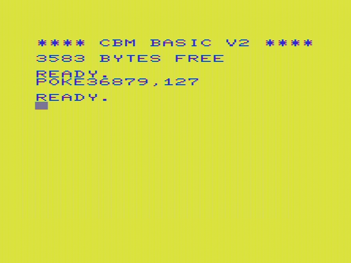
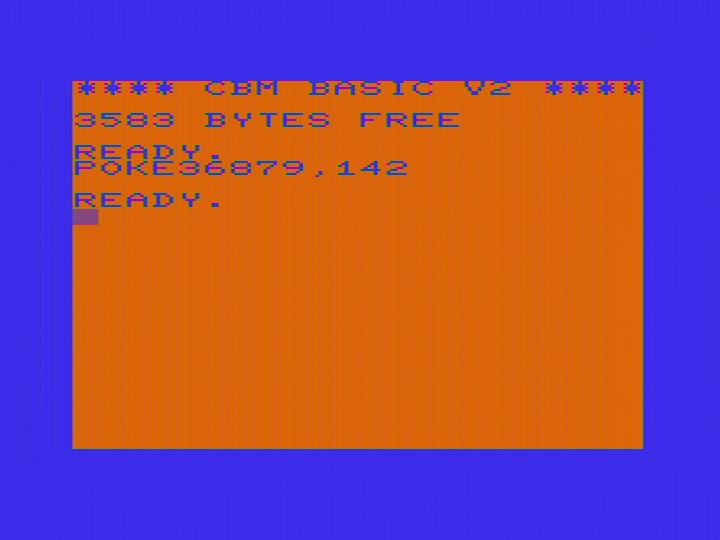
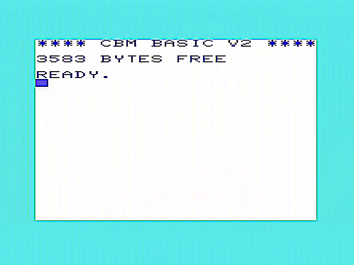
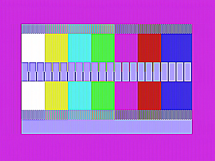
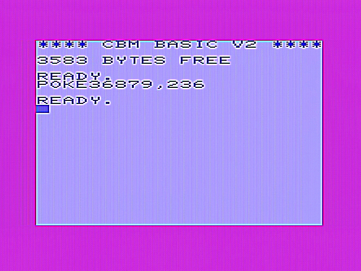
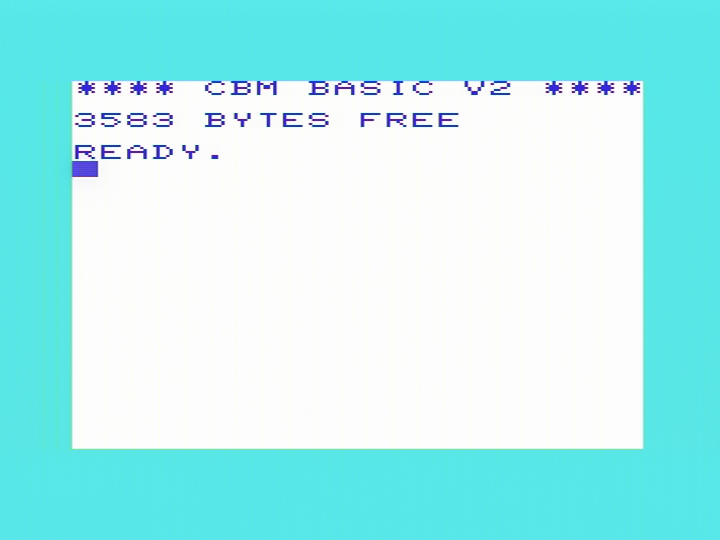
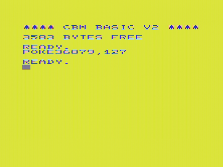
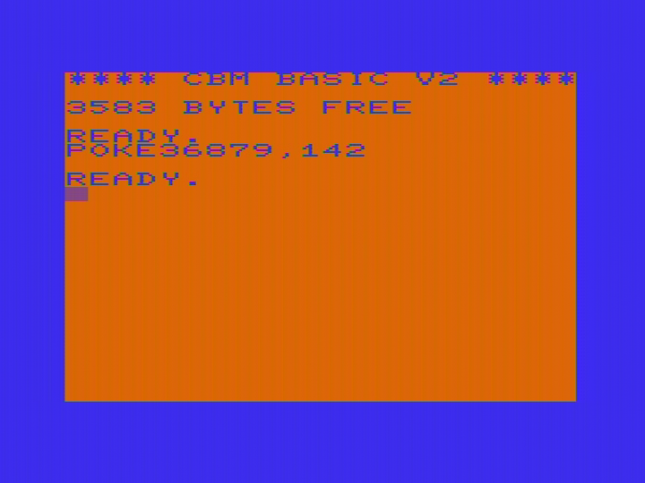
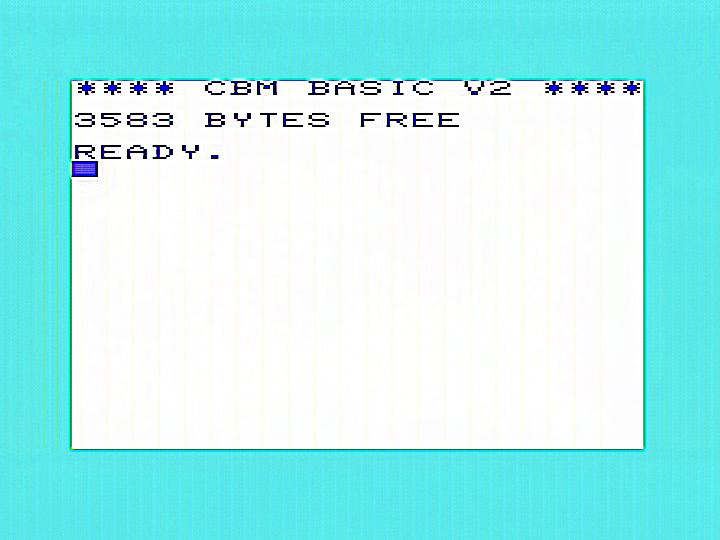
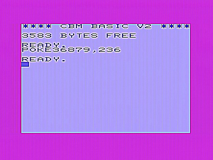
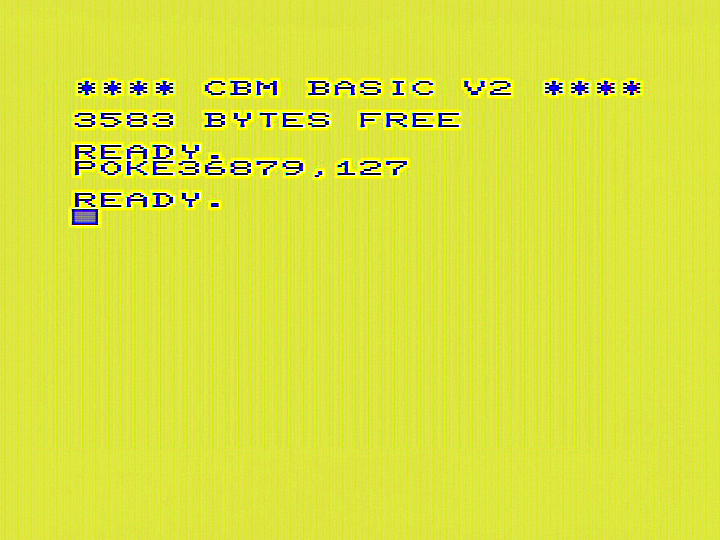
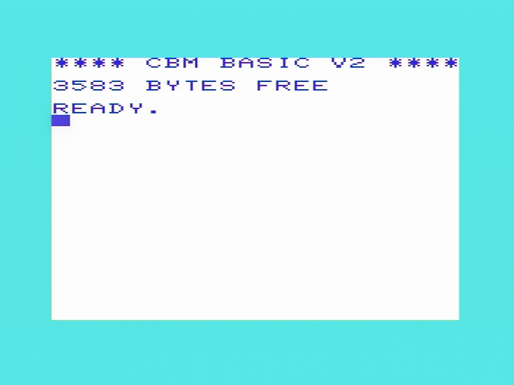
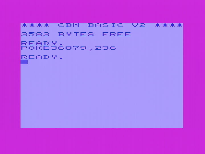
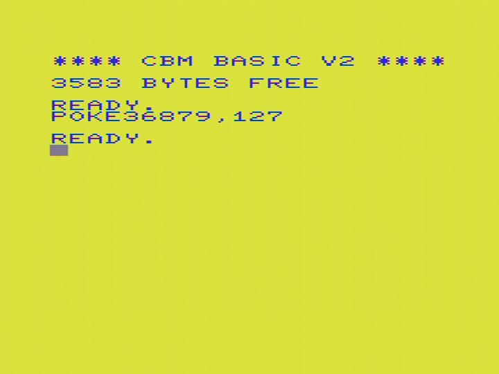
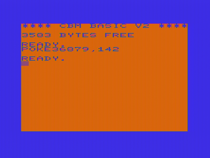
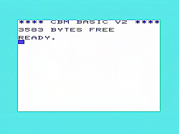
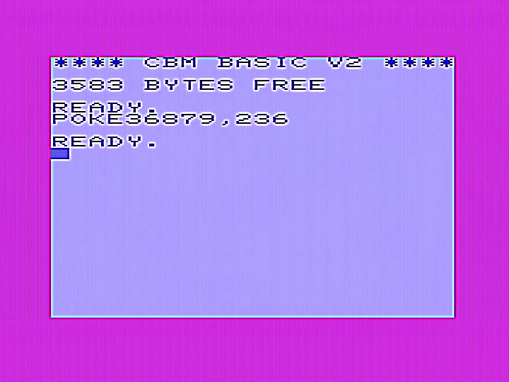
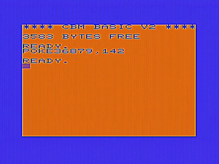
Below are images from a standard VIC-20 using the composite output. Unfortunately my digitiser tends to make composite video look soft in an attempt to eliminate dot crawl, so the images tend to look sharper on a normal monitor. The image softness tends to hide much of the jailbars and noise normally found on composite video. Images are: standard VIC boot screen, test pattern, a light blue screen (the 6561 does not do grey, this is the closest), a yellow screen that shows jailbars well, and an orange/blue screen that is also good at showing jailbars. A set of sharpened images is also included further below to allow better viewing of jailbars. Click on images for a full size view
Standard, unmodified VIC20CR.

A sharper view.

Converting the VIC-20CR to S-video.
One thing that is highly recommeded is to convert the VIC 20 to S-video. The VIC-20 really responds well to this, the image becomes amazingly sharp and clear. Much to my surprise an s-video conversion reduces jailbars considerably. I was actually expecting them to appear worse as the greatly improved sharpness should make them far more apparent. Closer inspection reveals that luminance jailbars are sometimes more noticeable (especially in light blue), but in almost all other cases they are noticeably reduced. This modification is an improved version of the one I developed quite a few years ago and which is documented in the VIC-20 Wiki. The earlier version is still satisfactory to use and still gives excellent results. Below are images taken of the VIC-20CR board showing the modifications needed to convert to S-video. Also shown are modifications to reduce jailbars which are explained in later sections below.
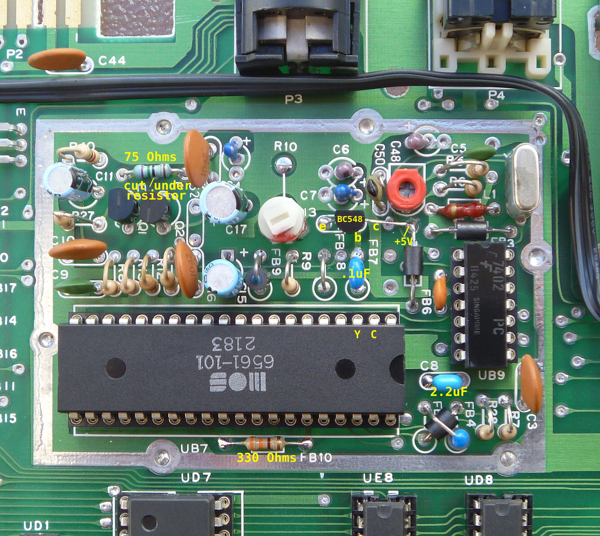
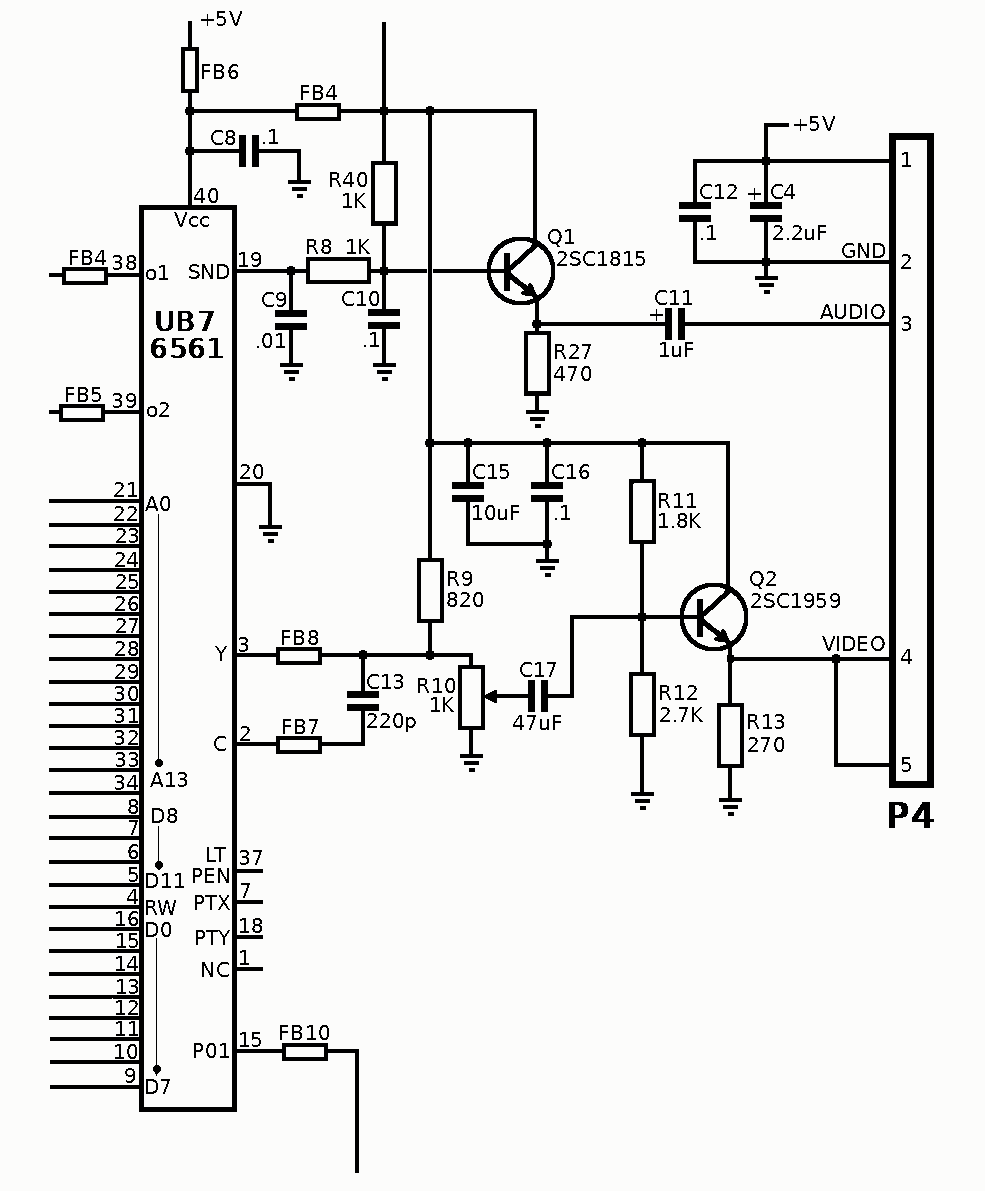
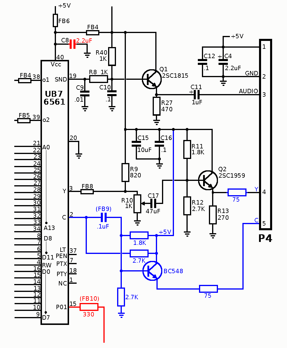
Schematics for the video section of the VIC-20CR (short board). Note that this is for the PAL version and that Commodore messed around with the design quite a bit, so your machine may have differences. On the left unmodified, on the right showing the completed modifications. Additions/alterations for S-video shown in blue, other jailbar reduction modifications in red.
* On the top of the PCB, cut the track above Q1 and Q2 and add a 75 Ohm resistor across the cut as shown.
* Remove FB7 and replace with a 0.1uF capacitor.
* Remove C13 and replace with a BC548 transistor. Emitter to the left pad, Base to the right pad, and Collector stretched across to the top of FB6 (+5V)
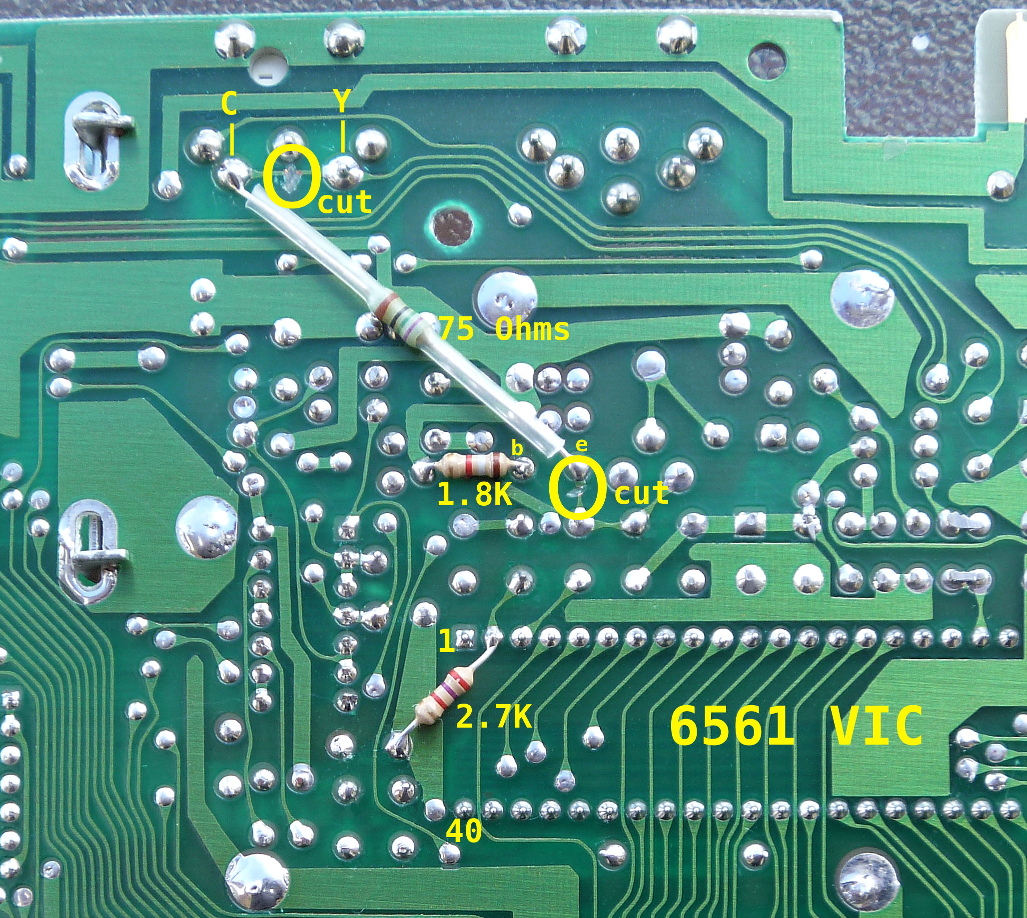
* On the bottom of the board, cut the PCB tracks in the two places indicated and solder a 75 Ohm resistor between the two isolated places (video output and emitter of the BC548). Use plastic tubing to insulate the resistor.
* Add a 1.8K resistor between the base of the BC548 and +5V as shown.
* Optional. Add a 2.7K resistor between pin 2 (C output) of the 6581 VIC chip and +5V as shown. This reduces blue/purple/cyan level if needed and may reduce jailbars in those colours.
* Using an oscilloscope, and with the monitor connected, adjust R10 so that the luminance signal at the DIN socket is 1V from the sync tip to the white level. Confirm the sync signal is 0.3V. If you don't have an oscilloscope try adusting for the best picture using the monitor you intend to use.
Other modifications in the images will be explained in later sections. Note that Commodore varied the design of the video section several times, so the parts layout on your board may vary with the one I started with, especially in regards to C13, it may be connected to the wiper of R10 instead of being located in the spot allocated for it on the PCB. Remove it and connect the transistor in the same way as described above. There are third party modules out there that will give S-video output without cutting tracks. I don't know how well they will work when combined with the jailbar reduction mods described in later sections below.
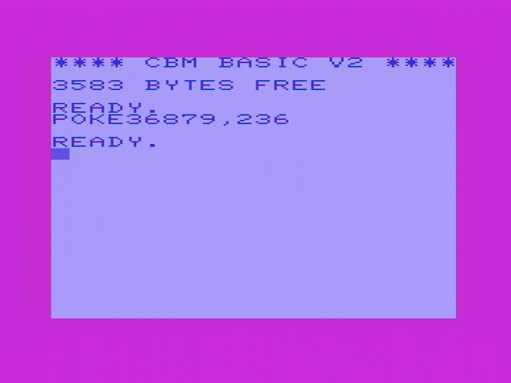
Below are images showing the effects of modifying for S-video.


A sharper view.


Improving Vcc filtering.
As far as I know, there is no "LumaFix" type device for the VIC-20, so we will have to rely on other techniques to deal with jailbars. One problem that was quickly identified is that the Vcc (+5V) supply on the 6561 VIC chip is poorly bypassed as there is only a single 0.1uF capacitor (on my machine). Replacing this capacitor, C8 on my machine with a 2.2 uF ceramic cleans up the 5V supply considerably. Jailbars in the luminance signal are noticeably reduced. You can of course, leave the original capacitor in circuit and add the new one across it. You can also use a fairly high value electrolytic capacitor too. I tried 100uF which worked well. Below are images after this capacitor was added.

A sharper view.


Altering clock P01 risetime.
It seems most of the spurious 1MHz signal found in the chrominance output in the VIC-20 is coming from the P01 system clock. This is generated in the 6561 VIC chip and is output on pin 35 through a ferrite bead (FB10). I have found that replacing FB10 by a 330 ohm resistor cleans up most of the jailbars in the chrominance signal. Of course messing around with a system clock can cause stability problems. A higher resistor will reduce the jailbars more, but the risk of system instability also goes up. I tested a 470 Ohm resistor and that worked fine, but to be safe, I chose to use 330 Ohms.

A sharper view.


Once all the modifications are done, the VIC-20 goes from having apallingly bad video quality to being nearly as good as RGB, assuming you have a good monitor.
Back to jail!
Back to main Amiga page.
Introduced 29th June 2023. Version 1.0