Jailbars - a new approach.
How to do it in the C-64 "long board"
The C-64 "long board" was the original version usually housed in the "breadbin" style case. Like other computers made by Commodore you will need to be aware that there several different versions which may vary from the one as shown here with PCB assembly No.250407. There are several ways to reduce or even eliminate jailbars as described below. Due to the complexity and poor PCB layout of these early version C-64s, the modifications required are somewhat more complex than in other, later designs. While not completely in the scope of this article, an improvement in display quality can be obtained by using an RF modulator replacement. Unfortunately many of these are designed for the C-64C or C-128, and they do not fit into the earlier C-64. This means that the Supervideo I tested on the C-64C is not compatible, and so I couldn't test it. Instead I tried a Lumafix 64 with a different RF modulator replacement that lacks the AEC cancellation feature.
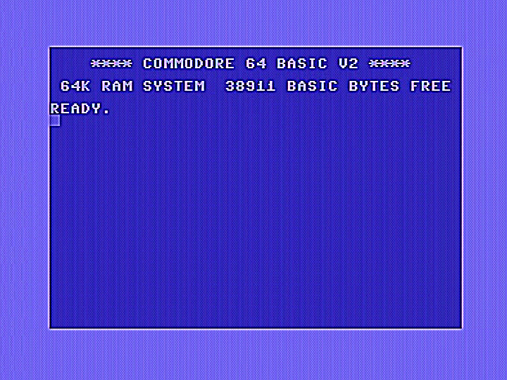
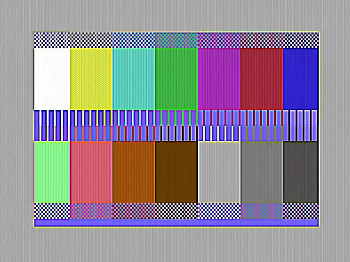
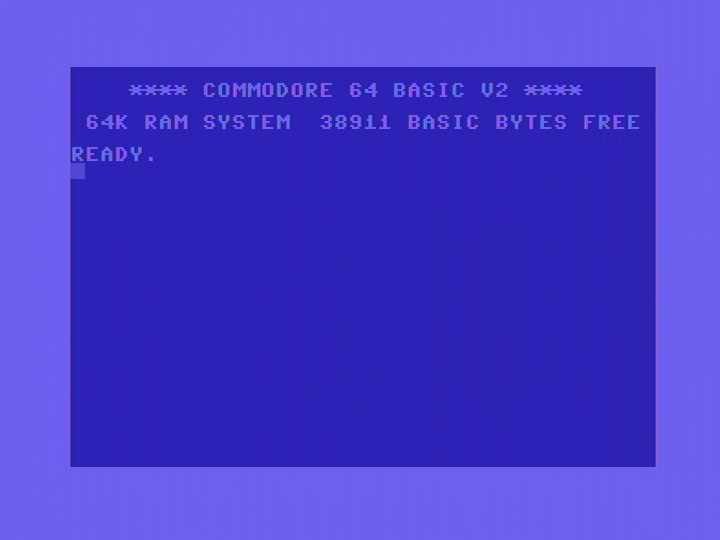
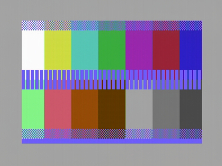
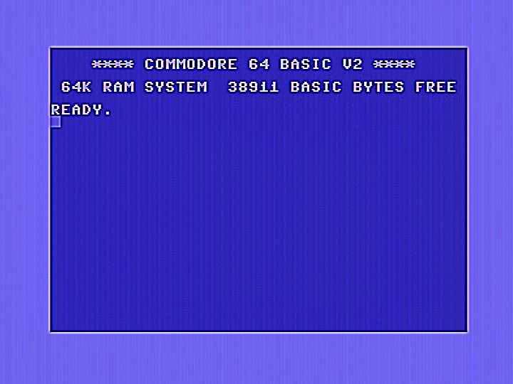
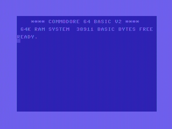
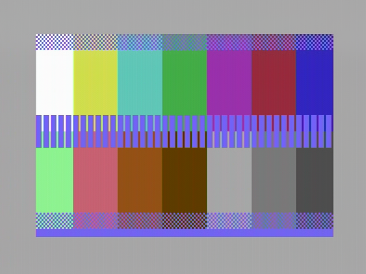
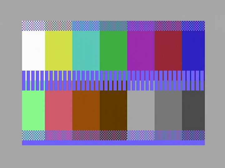
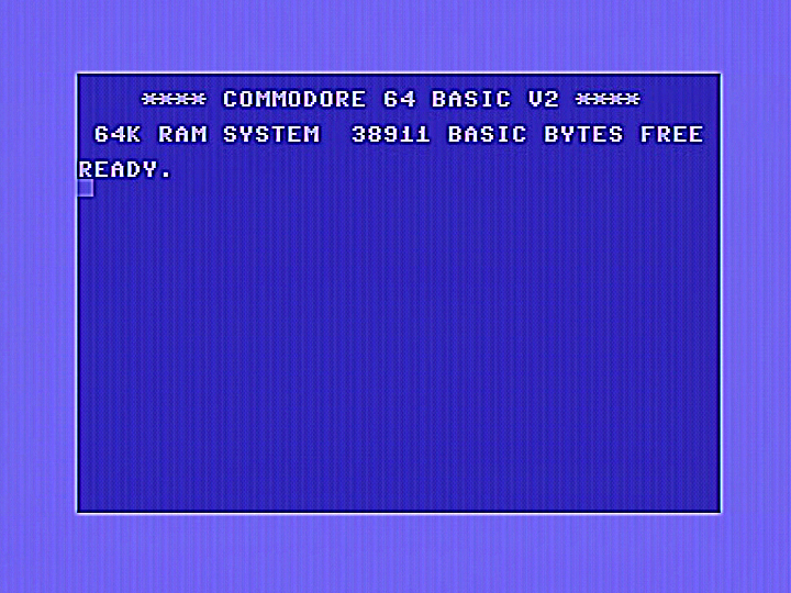
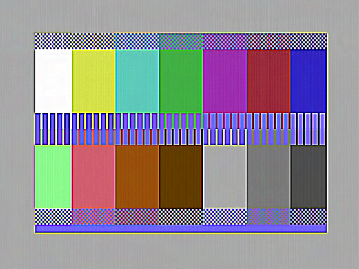
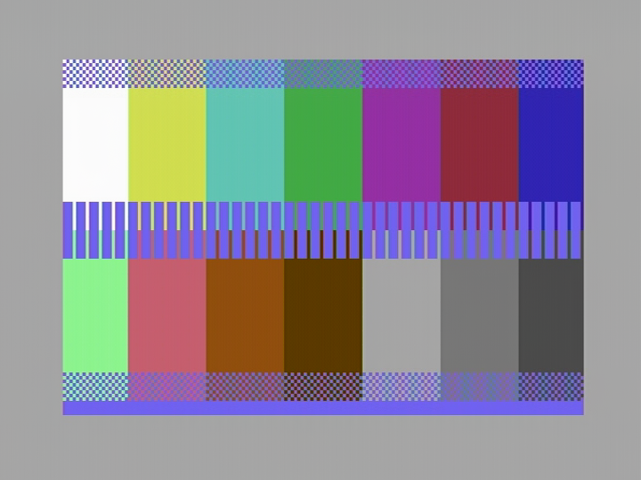
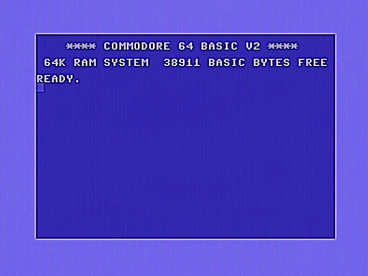
I have included images to show the effects of the various modifications on jailbars. Images were obtained by direct digitising of the video signal from the computer. In some cases differences have been subtle, so I have included two sets of images, unprocessed on the top, sharpened on the bottom. The sharpened images make it easier to see the jailbars and other artifacts. Note the very fine "mesh" like apperance on the boot screen and very fine vertical lines in the coloured areas of the test pattern. This is cause by crosstalk from the chroma signal breaking into the luminance signal. The C64 has a poor PCB layout with tracks for luminance and chrominance running next to each other causing crosstalk. To make matters worse, the chrominance signal is way too high in level, and this will need to be reduced to minimise the effect. The standard C-64 boot screen is shown on the left, and a special test pattern on the right. Jailbars are often more noticeable on some colours compared to others. The first set of images below show jailbars on a standard unmodified C-64. Click on images to view in full size.
C64 without modifications.
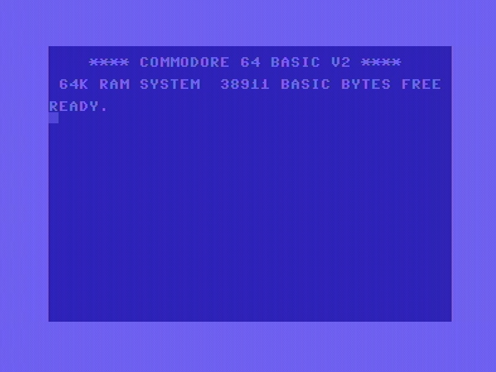

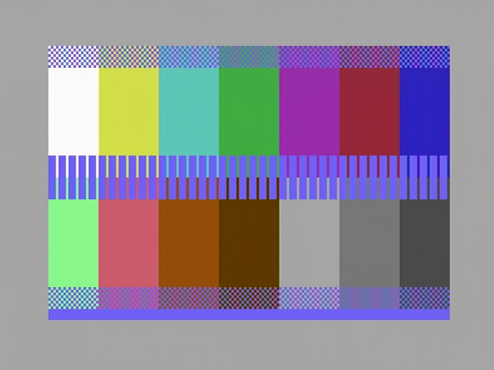
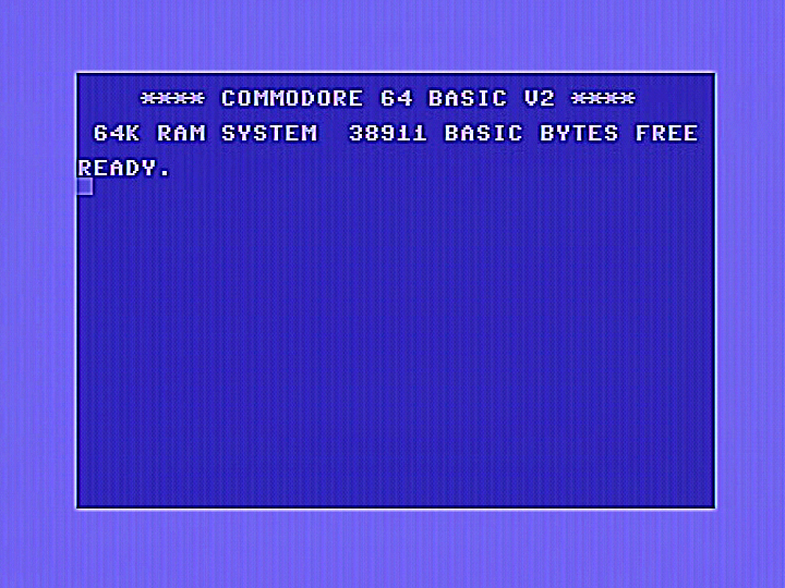
A sharper view.
Lumafix
Essentially, Lumafix works by taking a clock signal that causes jailbars, inverting it and then feeding it back into the luminance output pin by a controlled amount. This cancels out the interfering clock signal. In most C-64s, the AEC signal is the one that causes the most problems, though the LumaFix allows cancellation of the Phi0 clock signal found on pin 17 as well. In addition the Lumafix allows the user to reduce the chroma signal level as it is normally too high and can break into the luma signal, causing a fine "mesh" like pattern. I should mention that my C-64 already has a replacement RF modulator which also allows reduction of the chrominance signal. In this case I had already adjusted it to the correct 0.3V colour burst level, however due to poor PCB layout there is still significant crosstalk.
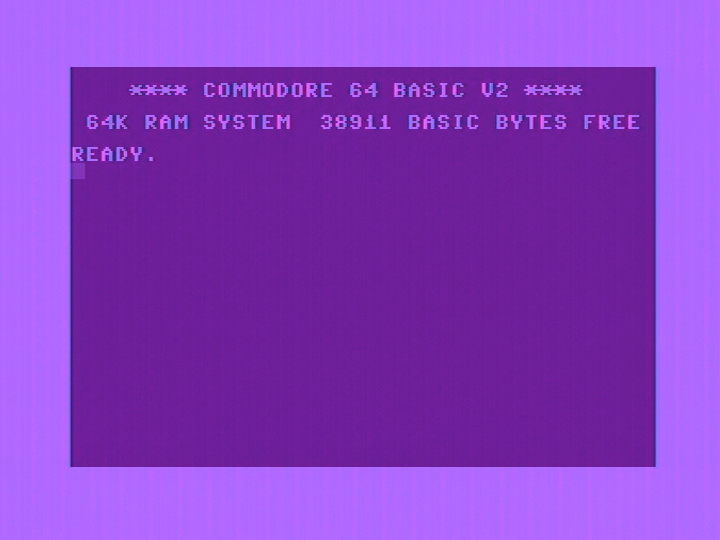
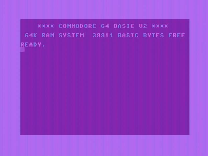
Images show results using a Lumafix 64 with no other modifications.
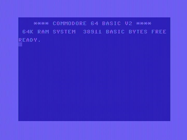

A sharper view.


Note the fine mesh pattern caused by the excessive chrominance level has now been reduced by use of the chrominance level adjustment in the Lumafix. Due to the poor PCB layout in the C64, in order to get this improvement, I had to reduce the chrominance level well below the correct value of 0.3V (colour burst), and if I reduced it any further, the colour will become noisy.
Luminace shielding method
Bear in mind most of the modifications described below will involve modifications to your C64, mainly component substitutions and sometimes a PCB track will need to be cut. ,
Due to the poor PCB layout, the luminance channel is susceptible to picking up interference from other signal sources nearby. This includes clock signals, (especially AEC) and the chrominance signal as the PCB track for this runs right next to the luminance track. Shielding the luminance signal should drastically reduce this interference.
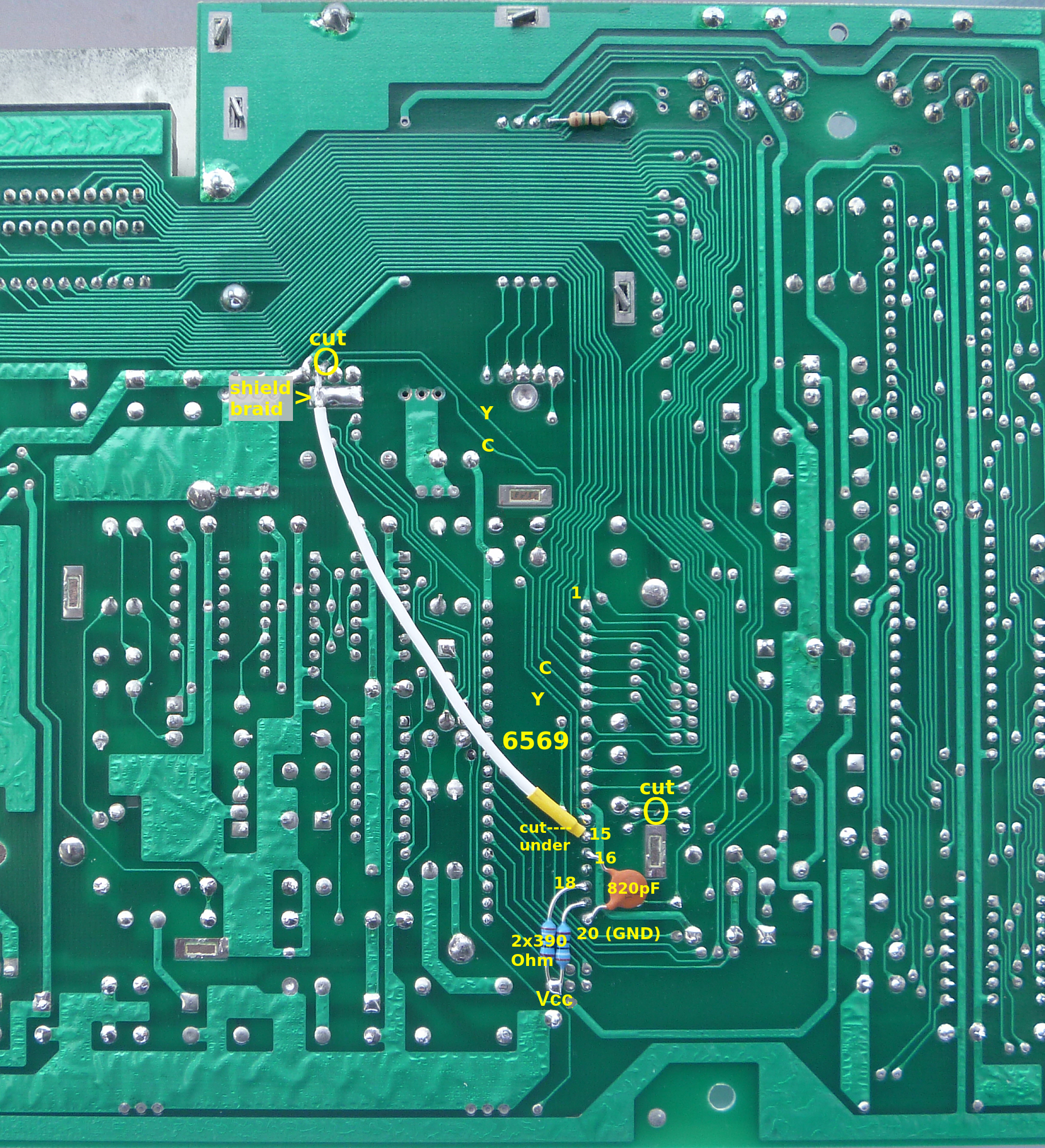
In order to perform this modification, you will need to cut the PCB trace as close as possible to pin 15 (luma out) on the 6569 VICII chip. Cut the other end of the trace as close as possible to the luminance input pin on the RF modulator as indicated in the picture. Shielded wire is then used to connect these two isolated points. The shield braid at the modulator end should be soldered to the ground point as shown in the image above. The shield on the other (pin 15) end was cut as close as possible to the end of the wire and insulated with heat shrink tubing. It is not connected to anything. The best kind of shielded wire is the small diameter type using Teflon (PTFE) insulation. Note that all the other additional modifications described further below are also shown on these images.
As can be seen in the images below, shielding the luminance channel on its own has resulted in a significant improvement in jailbars as well as eliminating the fine mesh and line patterns caused by chrominance crosstalk. Bear in mind due to the replacement RF modulator already fitted, the chrominance level has already been adjusted to its correct 0.3V at the colour burst, so I was already getting superior performance compared to a C-64 with a standard modulator.
A sharper view.

Shielding with Lumafix.
I repeated the Lumafix experiment, this time with the luminance channel shielded and got the results shown below.
A sharper view.


Using Lumafix with a shielded luminance channel results in superior performance compared to Lumafix on its own. This is the case on other machines I have tried which seems to indicate that shielding makes it easier for Lumafix to do its job. The chrominance signal now does not need to be excessively reduced in order to reduce "mesh" or fine lines on the image. I recommend that Lumafix users should do this modification.
Shielding with AEC bypass.
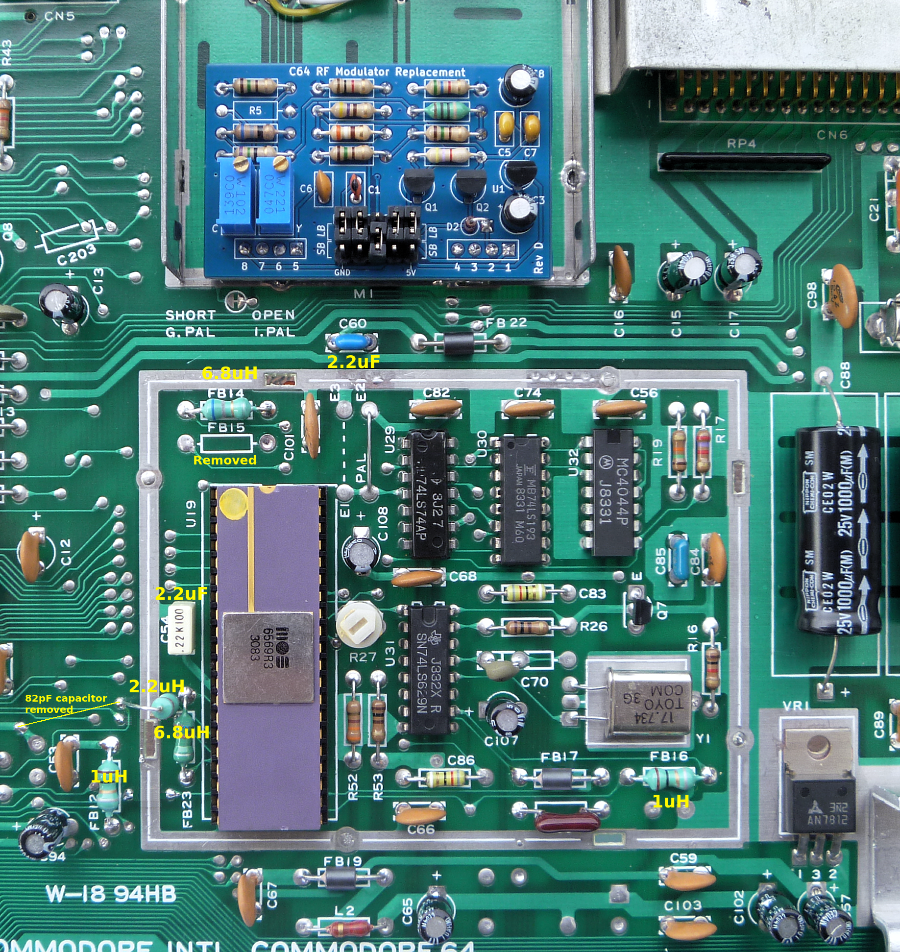
In this experiment, the track to pin 16 (AEC) on the 6569 chip was cut and a 2.2 uH inductor added across the cut track. An 820 pF capacitor was connected from pin 16 to ground. An existing 82pF capacitor that had apparently been 'bodged' in during manufacture was removed, though there is probably no harm in keeping it in position (see the 'top' image above). The intention being to slow the rise and fall times of this clock, making it less likely to cause interference. This was described in greater detail in the C-64C section. Note that I had used a 520pF capacitor in the C-64C instead of the 820pF used here. The Lumafix was removed for this and all subsequent experiments as altering the waveform of the AEC signal would prevent the Lumafix from working properly.

A sharper view.
This was a bit disappointing, making these changes failed to cause much discernable improvement, except possibly for some grey areas in the test pattern. This is most likely because shielding already prevents most interference from clock signals like AEC from affecting the luminance channel. I kept this modification in place for later tests as they still usually help when combined with later modifications.
Shielding with AEC and power bypass.
For this test, the previous two modifcations were kept in place. The 6569 chip requires two supply voltages, Vcc at +5V on pin 40 and Vdd at +12V on pin 13. As in most other machines, they could do with better filtering to reduce noise. To achieve this, C60, a 0.1uF capacitor was replaced with a 2.2uF ceramic capacitor, and C54, also a 0.1uF capacitor was replaced by a 2.2uF ceramic capacitor. FB12 was also replaced with a 1uH inductor. I did try a larger one, but it did not provide any further improvement.

A sharper view.

Not much change here, possibly some grey areas had a slight improvement. This modification was also kept in place for later tests.
Shielding with AEC, power and RAS / CAS adjustment.
The previous modifications were all retained for this test. The 6569 generates RAS & CAS signals for the RAM, which are output on pins 18 and 19. Jailbars caused by these signals were reduced by connecting each pin through a 390 ohm resistor to Vcc (+5v). This has the effect of increasing the risetime of each signal, without reducing its amplitude. A typo in the previous version of this document specified a connection to GND, not Vcc. While it would not have caused any problems, connection to GND would have been ineffective.

A sharper view.

Increasing the risetime of the RAS/CAS signals as shown here has made a worthwhile improvement to jailbars. This modification, in conjunction with previous modifications gave the best results, and is recommended for fussy users like me. Using a Lumafix with shielding as described above is recommended for users who want good results with not too much effort.
Jailbars in chrominance signal.
This version C-64 has a strange and subtle form of jailbars in the chrominance signal. They are mostly visible as subtle red fringing on alternate characters on the boot screen, and also visible as wide alternating colour bands in the dot patterns in the test patterns shown above. In addition there is a random, 50% probability determined at powerup where you may see some faint, wide jailbars in some large coloured areas, especially brown. It appears to be caused internally inside the 6569 chip, and it seems to be impossible to correct in any meaningful way. The images below have been processed to make the jailbars and character fringing very visible. You can see the two different states they can be in at powerup.
Some small improvements were achieved by replacing FB16 with a 1uH inductor. Some further, very small improvements were obtained by replacing FB14 with a 6.8uH inductor. A larger inductor could possibly provide further improvement, but there will be increasing amounts of chroma delay, which is undesireable. Replacing FB23 with a 6.8uH inductor helped to make the appearance of the jailbars more consistant, instead of having them worse 50% of the time and better for the other 50%. Compared to a rev 5 6869, a rev 3 seemed to have less colour jailbars, especially in the blue boot screen, at least with the two chips I tested with.
The later short board versions using the later 8565 VICII chip appear to have no colour fringing in characters and the 50% random jailbars don't occur. It is possible to replace the 6569 with an 8565 by disconnecting pin 13 (VDD) from 12V and connecting it to 5V. The luminance output pullup resistor on pin 15 (usually located inside the RF modulator) will also need to be changed from 470 ohms to 1K. This will almost completely eliminate those colour jailbars and as a bonus, the 8565 also runs much cooler than the 6569.
Back to jail!
Back to main Amiga page.
Introduced 28th June 2023, Updated 23rd July 2025. Version 1.3