Jailbars - a new approach.
How to do it in the C-128DCR
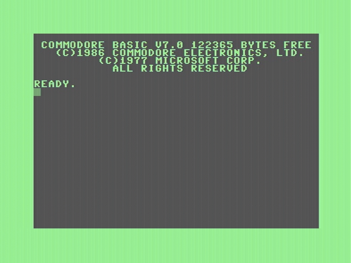
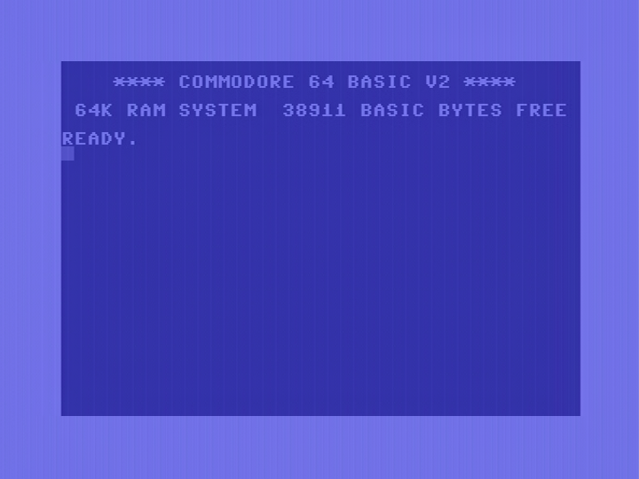
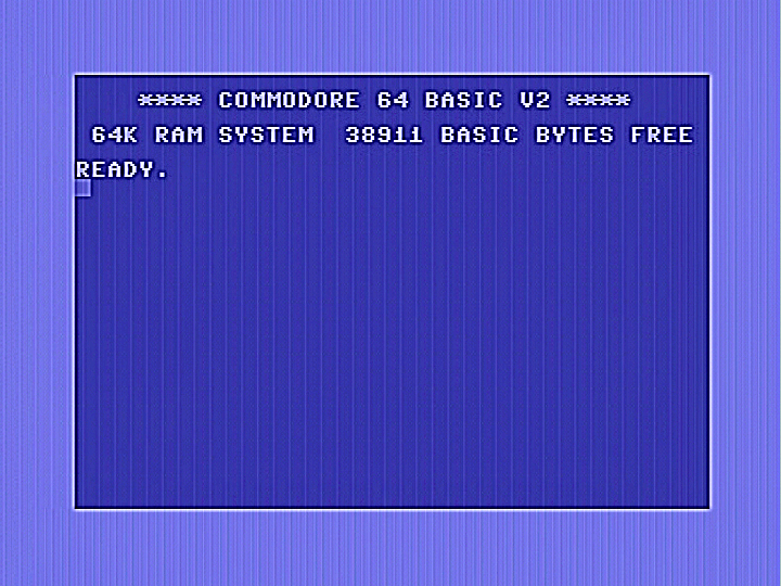
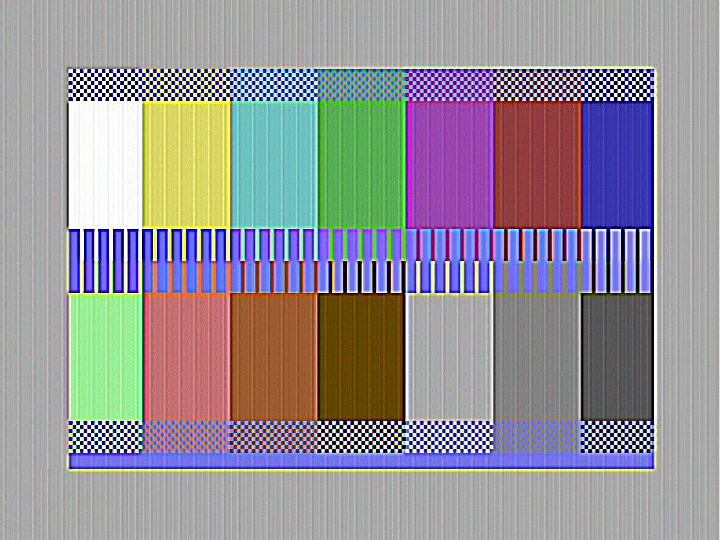
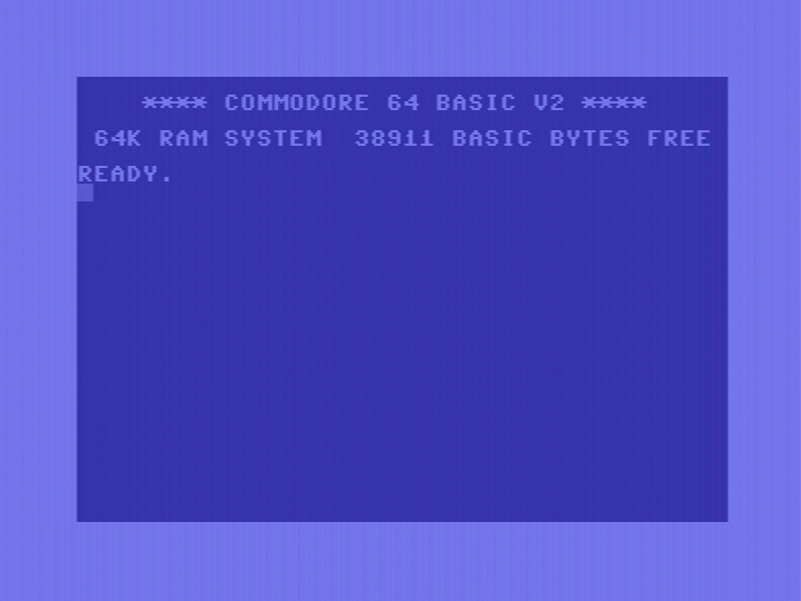
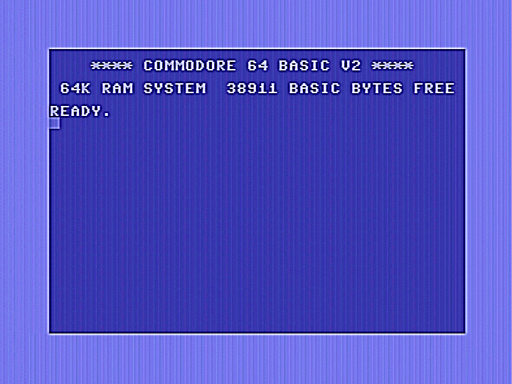
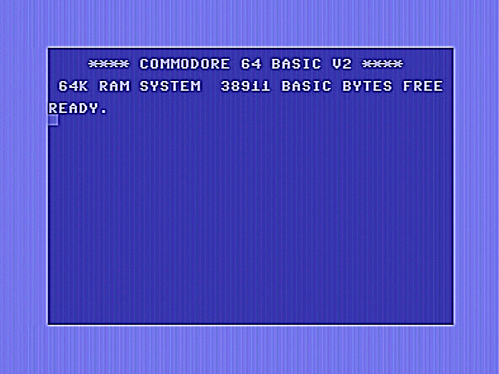
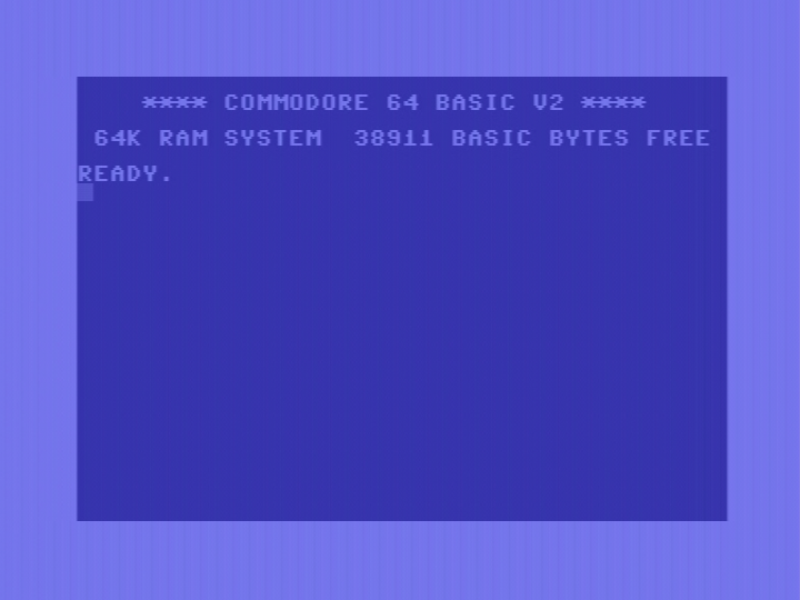
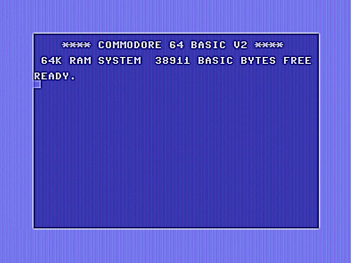
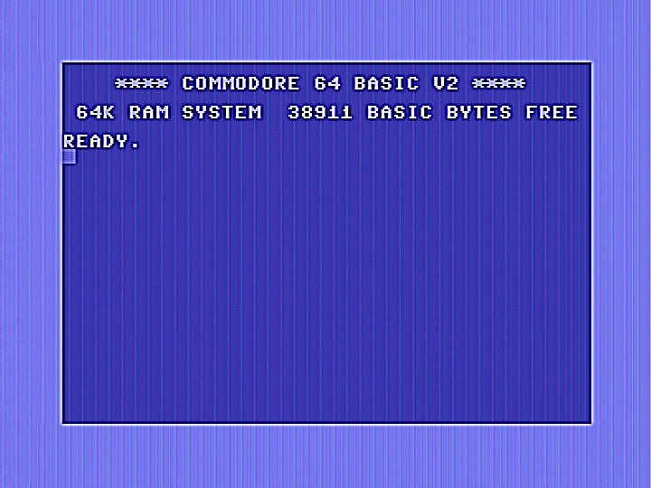
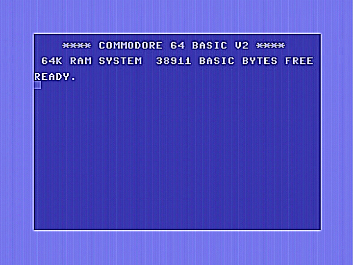
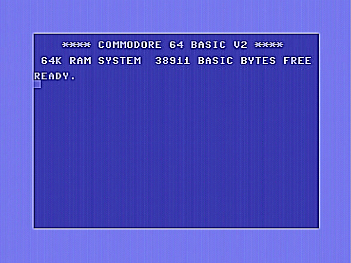
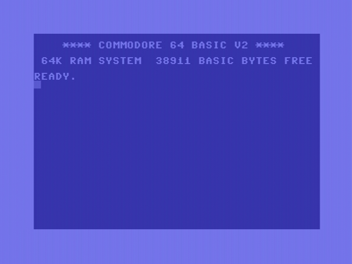
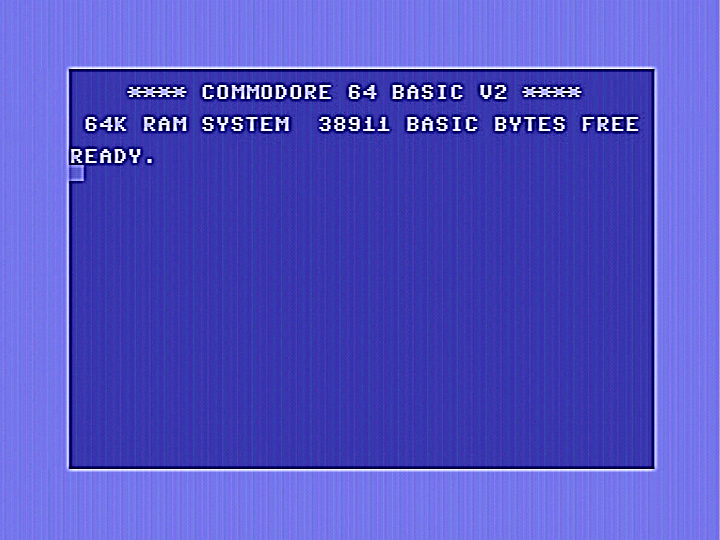
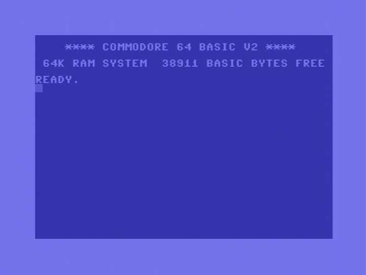
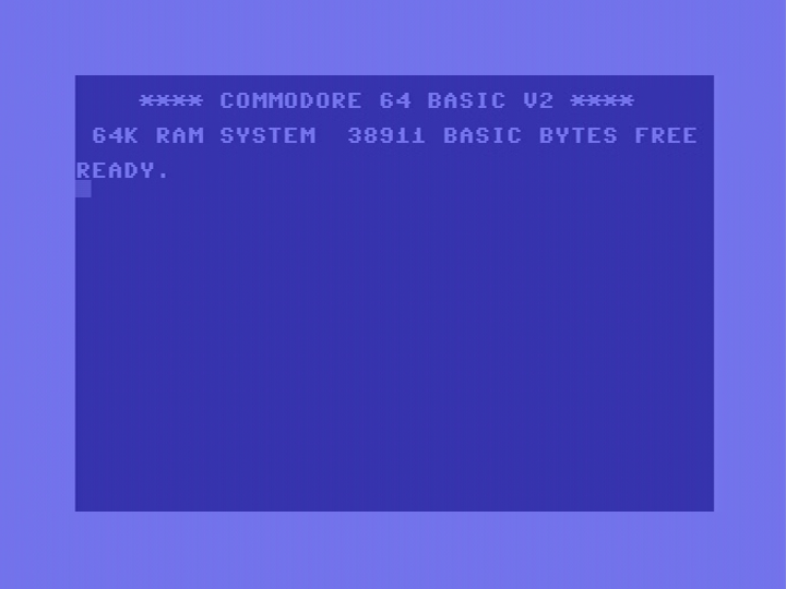
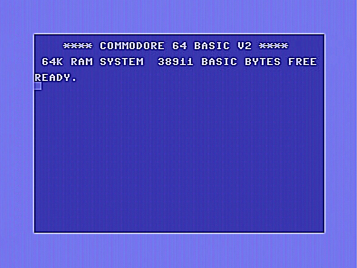
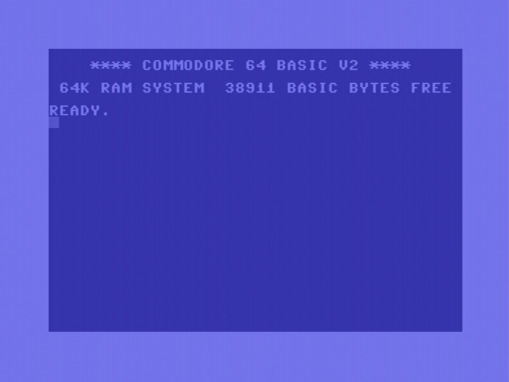
The C128DCR is notorious for having very possibly the worst jailbars in any Commodore computer. The 1MHz clock signal is located right next to the luminance output pin on the 8566 VICII chip causing severe crosstalk. Despite having the same 8566 chip as in the C128, the C128DCR is considerably worse, possibly because the luminance signal track in the C128DCR PCB is longer than in the C128, allowing it to pick up more jailbar causing interference. Below are images from an unmodified C128DCR. Images were grabbed straight from the video output. The jailbars in my C128DCR seem to be somwehat less noticeable than what I have seen on other machines. Perhaps this is simply manufacturing tolerances or perhaps already having a new RF modulator replacement in my machine has reduced jailbars a little. At this point its worth noting how the jailbars look rather different in the border compared to the centre of the screen. This indicates that border jailbars appear to be coming from multiple sources compared to the simple 1MHz lines in the centre. This may make it harder to eliminate them compared to in the centre.
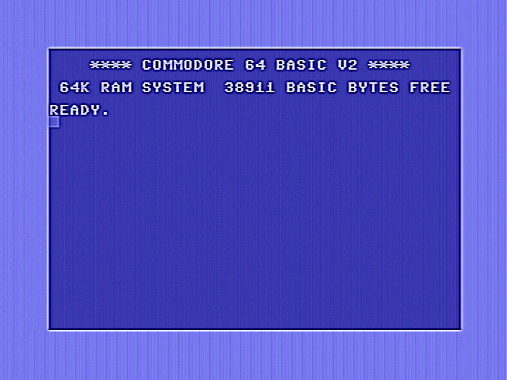
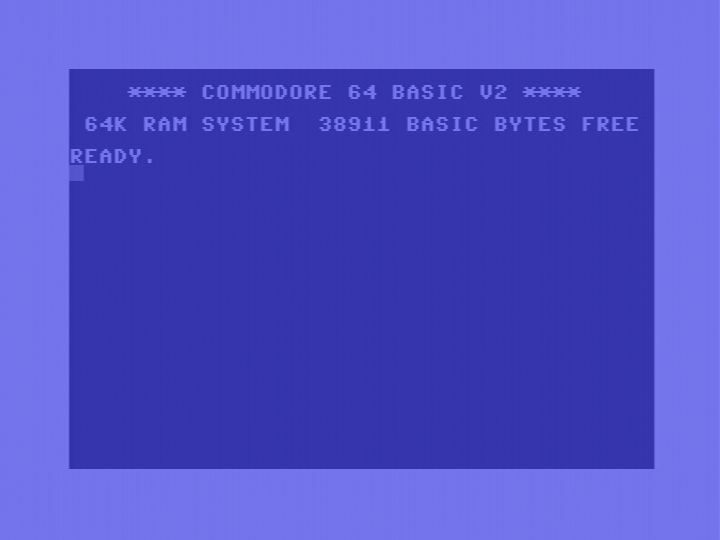
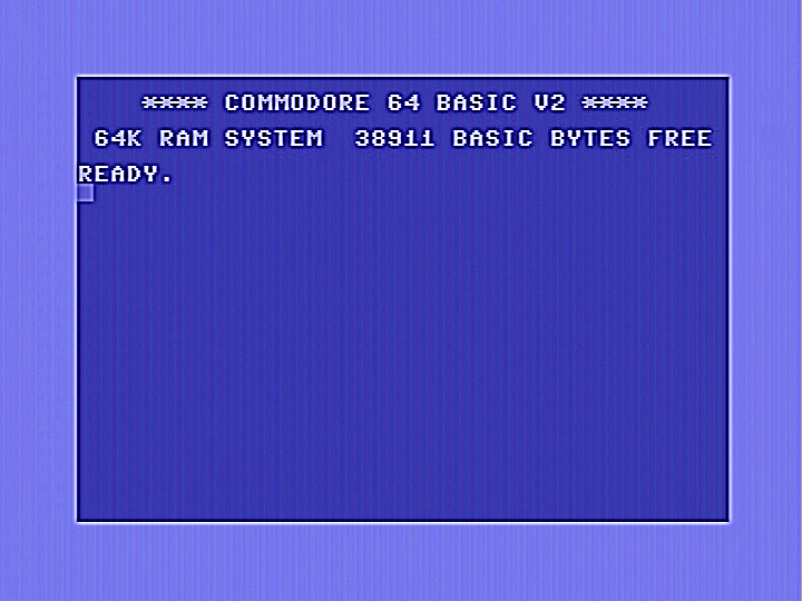
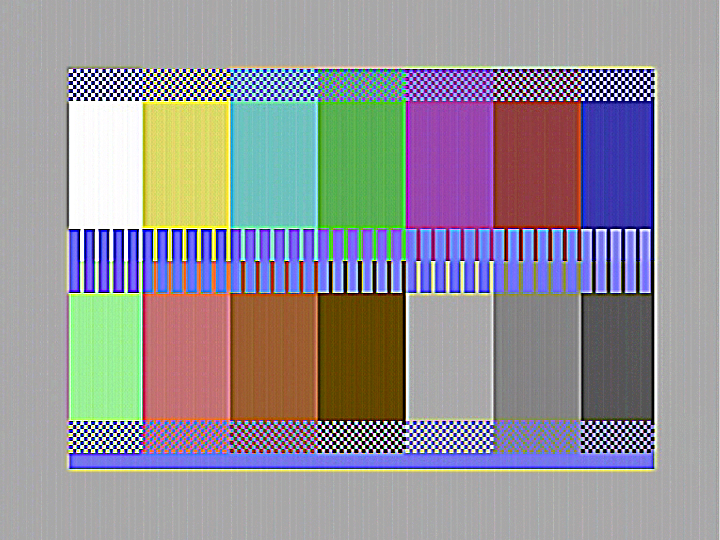
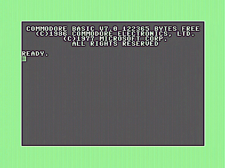
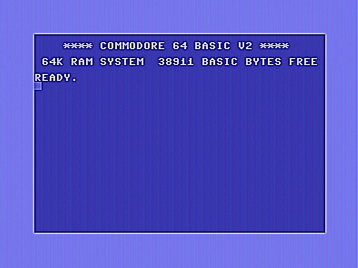
All images show the C128 boot screen, the C128 in C64 mode, and a special test pattern. The top row of each set of images are not enhanced, the bottom row has been considerably sharpened to make the jailbars more visible. This will also apply to all further images displayed below. All images showing results of modifications further below on this page should be compared with this set of images immediately below. Click on images for a full size view
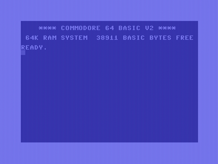
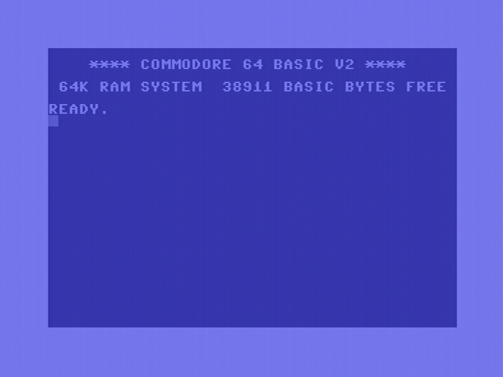
Standard, unmodified C128DCR.

A sharper view.

Adding a Lumafix 128.
The most common technique to deal with jailbars is to install a small device that takes one or more of the offending clock signals, inverts them, and then feeds them back into the luminance signal by a controllable amount. This hopefully cancels out the jailbar signal, leaving a nice clear image. There are a variety of these devices. Some of them plug into the 8566 socket, with the 8566 plugging in on top. Others are incorporated into RF modulator replacement units. The one I tried here is a "Lumafix128". It has the ability to handle five different clock signals. In my case I found that the first two adjustments (for 1MHz and /RAS) seemed to do all the work, the other adjustments didn't provide any improvements. It is worth noting that unlike the C-64 version, the Lumafix 128 does not have a setting for the AEC clock signal. Most likely because this clock is not adjacent to the luminance output on the 8566 chip, and therefore does not cause interference. I tested this later, and found that there was no value in trying to cancel out this clock signal. Each clock in use by the Lumafix reduces the sharpness slightly, even if the adjustment is turned all the way off, so switches are provided to switch off unused clock signals. The image gets rather smeary if all are turned on, so make sure you have only the ones you need turned on.
The images below have only the 1MHz clock signal activated in the Lumafix. It provides some improvement in the centre of the screen, but does not help the borders.


A sharper view.


The next set of images has only the 2MHz clock signal activated in the Lumafix 128. Results are similar to the 1MHz clock.


A sharper view.

The next set of images has both the 1MHz and the /RAS signal activated on the Lumafix, as recommended in the instruction leaflet. This gave the best results. I did try combinations of the other signals, but was unable to get any further improvement using those. They may work better in other machines, so it is always worth trying them for yourself. While jailbar removal was excellent in the centre of the screen, the borders were not improved at all. There are ways to improve this, as will be revealed in a later section on this page. Note that the image has lost some of its sharpness as there are now two clock signals activated.


A sharper view.


I was a little disappointed with the performance of the Lumafix. One reason may be the requirement to raise the Lumafix on stacked sockets to allow it to clear components and shielding on the PCB. Doing this increases the amount of stray capacitance between the luminace pin and the various nearby clock signals, especially the adjacent 1MHz clock. In order to test this, I removed the metal shielding from around the video area and replaced C28 (0.22uF, 16V) with a physically smaller alternative. I was then able to remove the IC socket that had been needed for the Lumafix to clear those items. I got a small improvement. Images shown here were made before this modification.
Adding a Super Video.
The Super Video is a drop-in RF modulator replacement that is compatible with all versions of the C128 as well as the short board version of the C64. This device has a single channel available to allow one clock signal to be inverted and used to neutralise jailbars, in the same way as the Lumafix 128. Although the clock input on the PCB is labelled 'AEC', for C-64 use, any other clock signal can be connected. While using AEC was ineffective on the C128, I did try the 1MHz clock signal as shown below, and got slightly superior results to using the 1MHz clock on the Lumafix 128. Of course the Lumafix can handle more than one clock signal, and doing so gives better results. Other clock signals were tried, but they were inferior to the 1MHz clock, and therefore I did not record images of results.


A sharper view.

Bypassing clock signals.
Another possible jailbar reduction technique is to modify the clock signal(s) that causes the jailbars. I found this was really effective in the short board version of the C-64, and was ridiculously easy to implement. A 560pF capacitor was connected between the AEC pin and ground in the C-64C. This capacitor slows down the rise and fall times of the AEC signal, making it less likely to cause interference. Of course, care needs to be taken as modifying a clock signal too much can cause problems. I tried this in the C128DCR, but bypassing the AEC signal was ineffective. I tried it on the 1MHz and 2MHz clocks as these seem to be the main causes of interference. I got a worthwhile improvement in jailbars by bypassing the 1MHz clock as shown below.


A sharper view.

As the 2MHz clock pin is located a distance away from the luminance pin on the 8566, I was not expecting any worthwhile results. A very slight improvement was obtained as shown below. I did not try bypassing both clocks at the same time.


A sharper view.

Shielding the luminance signal.
Given that jailbars are caused by crosstalk from clock signals getting into the luminace channel, it would be desirable to prevent this in the first place by shielding the luminance channel. To do this the PCB trace is isolated from the 8566 VIC chip by cutting it as close as possible to pin 17. This is easier than in the C128, as the track is not hidden under the IC socket. The other end of the pcb track is isolated from the RF modulator by removing FB19. A short length of shielded wire is run from pin 17 of the 8566 chip to the luminance (Y) input of the RF modulator. The shield is soldered to the adjacent ground pin on the modulator as shown in the picture below. As in the C128 version of this mod, the shield at the pin 17 end was cut away as close as possible to the end of the wire, and some heatshrink tube was used to prevent shorts. You can see in the picture the PCB track between pin 17 and the modulator follows quite a long and convoluted path compared to the standard C128. Because of this, the C128DCR always had worse jailbars, even though my C128DCR seemed to be better than most. You could compare the before images at the top of this page with the before images on the C128 page to get an idea.
The blue wire shown is not part of the shielding modification. This is described in the sections explaining the use of a SuperVideo RF modulator to suppress crosstalk from the 2MHz clock on pin 23. This could alternately be connected to pin 18 if you want to do this to the 1MHz clock. Make sure this wire does not go near any luminance or chrominance signals. This wire is not used if you are using a Lumafix128.
While I didn't see any noticeable improvement, I soldered a 0.22uF surface mount capacitor between pin 48 (VCC) and an adjacent ground trace to provide some extra bypassing. Refer to the picture below.

Images below show the effects of carrying out shielded wire modification only. Jailbars are noticeably reduced, but work still needs to be done to reduce them to an acceptable level. Click on images to view in full size. The jailbars that were still visible looked more uniform than before. Previously they looked more "messy" in the borders and to the right of the active screen area. I suspect that shielding has more or less completely suppressed jailbars from all other clock sources except the 1MHz clock. While reduced, there is still crosstalk from the adjacent 1MHz and luminance pins, and within the 8566 chip itself, it being impossible to shield or isolate these. With this in mind, I would expect the LumaFix128 should now have an easier task of reducing jailbars in the borders and not just in the centre.


A sharper view.


Combining shielding with clock bypassing.
In this case I combined shielding of the luminace signal with bypassing clock signals to ground with a 560pF capacitor as already described above. I tried bypassing the 1MHz clock (pin18), the 2 MHz clock (pin 23), and AEC (pin 12). I also tried bypassing both the 1MHz and 2MHz clocks at the same time, each with a 560pF capacitor. Out of all these options, I got best results with the 1MHz clock only, so it is shown below.


A sharper view.


Combining Shielding with Lumafix.
In this case, I tried the Lumafix again now with the shielded wire modification. Previous attempts at using the Lumafix on its own were somewhat disappointing, however, once the luminance signal is shielded, the Lumafix really comes out into its own. Jailbars in the borders are now greatly reduced. Below is the Lumafix with only the 1MHz clock used.


A sharper view.

Similar results are obtained with only the 2MHz clock in use as seen below.


A sharper view.
As before, slightly better results were obtained with 1MHz & /RAS together as shown below. You may choose to use only the 1 or 2 MHz clock on its own and have a sharper image with slightly more noticeable jailbars.


A sharper view.


Combining Shielding with SuperVideo.
In this case I tried shielding with only the 1MHz clock being cancelled out using a SuperVideo RF modulator replacement. This device only allows cancellation of one clock. To do this I connected pin 18 (1MHz clock) to the AEC in pad on the SuperVideo. With this combination I got the best results out of any option I tried. Jailbars are practically invisible, even in the sharpened images as shown below.


A sharper view.


Combining Shielding with SuperVideo 2MHz clock only.
In this case I tried shielding with only the 2MHz clock being cancelled out using a SuperVideo RF modulator replacement. To do this, I connected pin 23 (2MHz clock) to the "AEC in" pad on the SuperVideo. I got really excellent results here too, though very slightly inferior to the 1MHz version. Below are examples of results.


A sharper view.

Conclusion.
In conclusion the best results, in order:
1: Shielding with SuperVideo using the 1MHz clock. Other RF modulator based solutions should give similar results.
2: Shielding with Lumafix128, using 1MHz and /RAS clocks. Probably let down by the 'stacked' construction that increases crosstalk.
3: Shielding with 1MHz clock bypassed with 560pF capacitor. May be improved by increasing the capacitor value, but be careful you don't cause problems.
Back to jail!
Back to main Amiga page.
Introduced 28th June 2023. Version 1.0