Jailbars - a new approach.
How to do it in the C-64C "short board"
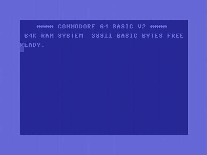
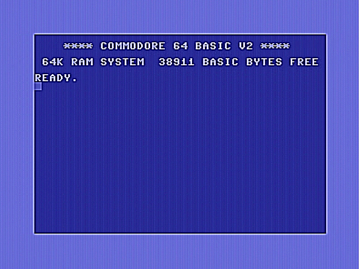
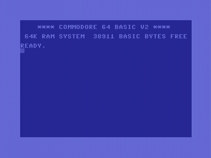
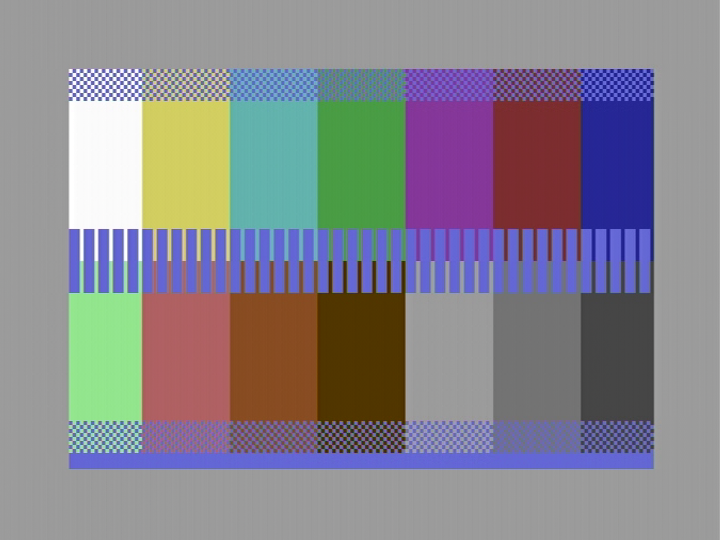
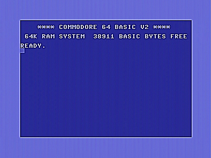
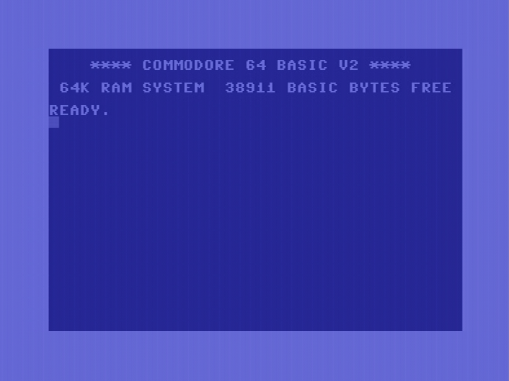
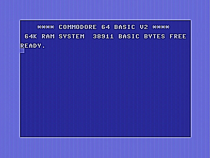
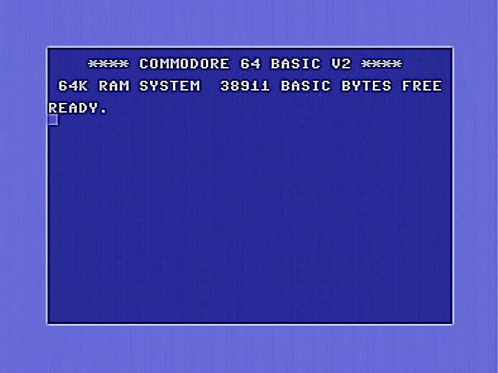
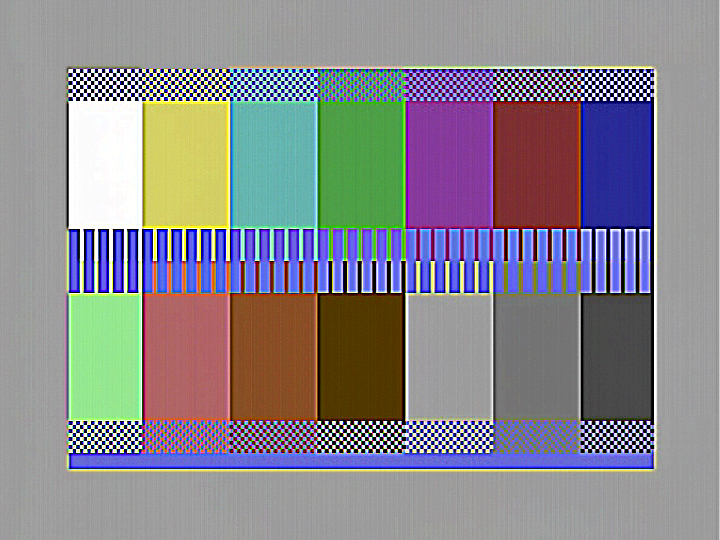
The C-64 "short board" was a later cost reduced version, found mostly in the C-64C with the smaller wedge shaped case. Jailbars in theis version are noticeably less than in the earlier breadbin C-64 with the "long board". Commodore had paid some attention to PCB layout and the chips. From my experiences, I found this version of the C-64 was the easiest to modify. There are several ways to reduce or even eliminate jailbars as described below. I have included images to show the effects of the various modifications on jailbars. Images were obtained by direct digitising of the video signal from the computer. In some cases differences have been subtle, so I have included two sets of images, unprocessed on the top, sharpened images on the bottom. The standard C-64 boot screen is shown on the left, and a special test pattern on the right. Jailbars are often more notceable on some colours compared to others. The first set of images below show jailbars on a standard unmodified C-64C. Click on images to view in full size.
C64C without modifications.


AEC bypass method
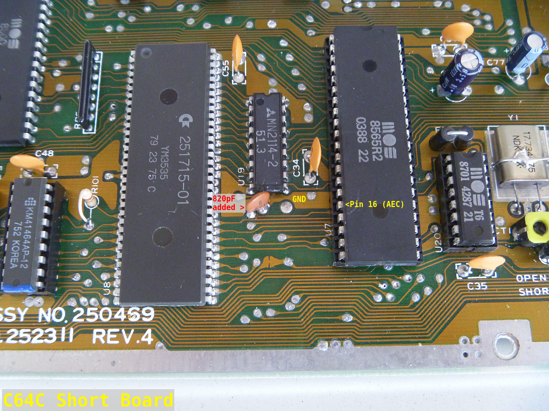
Very worthwhile results could be had by simply adding a 560pF capacitor between pin 16 of the 8565 VICII chip and ground. This has the effect of slowing the rise and fall times of the 1MHz AEC clock signal, reducing the crosstalk into the adjacent luminance output pin. You could, of course, increase the value of that capacitor to provide even further improvement, but care should be taken with this. Use too large a capacitor, and you could cause your C-64 to crash or do weird things. Note the image shows 820pF, I had taken it before I settled on using 560pF. While 820pF was perfectly reliable, I got very slighty better results with 560pF. You may want to experiment with this capacitor but if you increase the value much over 820pF, I advise a thorough test over a long period of time, perhaps using one of those test cartridges running over and over until you are satisfied the machine is stable. The capacitor can be easily added as shown, or it can be placed on the underside of the board in the same location. I had also tried bypassing the 1MHz clock but failed to get any worthwhile results.
Images below show the results. Compare them with the originals at the top of this page.


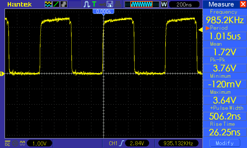
Below on the left is a standard AEC clock waveform. On the right is an AEC waveform after an 820pF capacitor is added to ground. The waveform will be somewhat less rounded when using 560pF. It is worth noting the voltage levels are quite low. Referring to the datasheet for the 6567, Commodore quotes an output high level at minimum 2.4 Volts, with no nominal value given. Also an input high level at minimum of 2.0 volts and maximum of Vcc. Therefore at least from a voltage level point of view, the signals shown are well within spec. I would guess the 8565 would have similar specs for clock inputs and outputs. Possibly Commodore designed it this way to try to reduce crosstalk. After all, the C-64C has less jailbars than most other versions of the C-64.

Super Video (Lumafix)
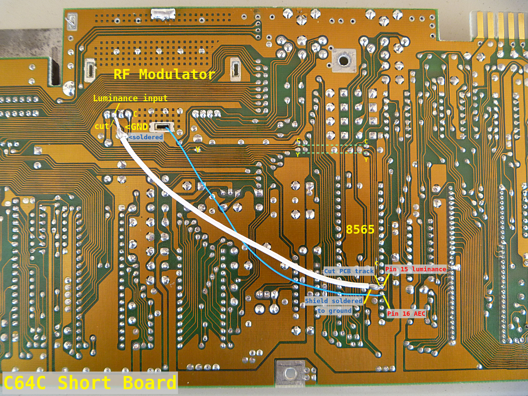
Essentially these work by taking a clock signal that causes jailbars, inverting it and then feeding it back into the luminance output pin by a controlled amount. This cancels out the interfering clock signal. In most C-64s, the AEC signal is the one that causes the most problems, though various LumaFix or RF modulator variants may also cancel out some other additional clock signals. In my case I don't have a dedicated LumaFix, but I do have a replacement RF modulator assembly that has an AEC cancelling feature built in. The RF modulater is called "SuperVideo" and is from Germany. It also provides an S-Video socket that is accessible through an existing hole in the C-64's case. In use, the AEC pad on the modulator replacement PCB is connected by an added wire to pin 16 of the 8565 chip. You can see this in the form of a blue wire shown in the picture of the C64 PCB in the "Luminance shielding method" shown below. I would advise routing this wire away from any video leads. I would expect LumaFix users may get superior results, as they can also cancel other interfering clock signals too. Note also that as LumaFix plugs into the 8565 VICII socket and is self contained, the added wire from pin 16 is not required.
Images show results using the AEC clock on a Super Video.

I also tried using the Super Video AEC input on several other clock signals in the C-64, especially the 1MHz clock, but did not get any useful results. I would expect the same would be the case with LumaFix users too. This was not a surprise to me as it is the proximity of the AEC pin to the Luminance pin on the 8565 that causes most of the problems.
Luminace shielding method
In order to perform this modification, you will need to cut the PCB trace as close as possible to pin 15 (luma out) on the 8565 VICII chip. Cut the other end of the trace as close as possible to the luminance input pin on the RF modulator as indicated in the picture. Shielded wire is then used to connect pin 15 and the luminance in pin, with the shield braids at both end being grounded as shown in the picture. The best kind of shielded wire is the small diameter type using Teflon (PTFE) insulation. Note that the blue wire takes the AEC signal from pin 16 and takes it to the AEC in pad on the SuperVideo RF modulator replacement, assuming that modulator is in use. This is described elswhere on this page, so for the purposes of adding the shielded wire only, it can be disregarded for the moment.
At first, it seems this was a failure, the jailbars were slightly worse than before. Possibly because Commodore had already paid attention to crosstalk in the design of the C-64C short board. But as we see later, shielding does wonders when combined with AEC cancelling using a SuperVideo (or LumaFix).


AEC bypass with shielding.
This was a bit disappointing too, adding the inductor and capacitor failed to cause any discernable improvement above what had been obtained by using the capacitor on its own without shielding.


Super Video (Lumafix) with shielding.
I then tried feeding the AEC clock into the AEC input of my SuperVideo, and got the results shown below. I would expect LumaFix users would get similar results.


And we have a winner! Shielding the luminance lead in conjunction with SuperVideo or LumaFix gives the best results. Closely followed by a SuperVideo or LumaFix on its own, and then by the 560pF AEC bypass capacitor on its own. If you don't have access to a SuperVideo or LumaFix, the 560pF capacitor gives excellent results for very little work.
Some people may be wondering why I didn't try the 560pF capacitor combined with SuperVideo/Lumafix. The thought had crossed my mind, but I reasoned that the LumaFix or SuperVideo would be expecting the interfering waveform from the AEC clock signal to have a particular shape. Adding the 560pF capacitor drastically alters it, meaning that the LumaFix will not cancel it out correctly. This may also explain the patchy results sometimes obtained, especially on machines with different motherboard and chip revisions.
Back to jail!
Back to main Amiga page.
Introduced 28th June 2023. Version 1.0