Overclocking the Phase 5 CSPPC
and
CS MK III boards
Overview.
The Cyberstorm PPC was a dual processor PPC604e / 68060 card clocked at 200 MHz and 50 MHz respectively, although there are other variants using slower speeds. There was also a later version that ran the PPC at 233 MHz. While it looks identical with the earlier versions, it has some internal changes that improve the ability to overclock it. This late version may have been sold in slower versions, though I have never seen any of these. In any case you can identify which version you have by going into the setup menu, selecting RAM and assuming you have the latest firmware, you should see some selection buttons marked 'Precharge'. If these are ghosted out and cannot be changed, you have an early version. Later in this article, I'll refer to the 200 MHz version as the 'early' version and the 233 MHz version as the 'late' version. The Cyberstorm MKIII is identical, but without the PPC chip and associated circuitry. MKIII users can ignore any references to the PPC in this discussion. The MKI and MKII versions of the Cyberstorm are completely different and the information here does not apply to them. Note that I cannot guarantee the accuracy of this information, nor can I accept any responsibility if you damage yourself or your hardware. Make sure you fully understand what you are doing before you atttempt to overclock this board. Bear in mind that the results I have obtained here may vary with what you may obtain on your system. Use these figures as a guide only.
My overclocked early version card (200MHz) has been running at 225 MHz for the PPC and 75 MHz for the (rev 6) 060 for many years with no problems in my tower-cased A4000. Desktop A4000 users will need to pay extra attention to cooling. I did have a few reliability problems earlier, which was traced to poor contact with the 200 pin CPU connector. This was caused by the board being mounted vertically in my tower case. Desktop users may not have this problem as their boards are mounted horizontally, and gravity may help hold it in place. I cured this problem by removing the original nylon clip-on type standoffs and fitting threaded standoffs of the appropriate size. The card was then fixed firmly in place with four screws.
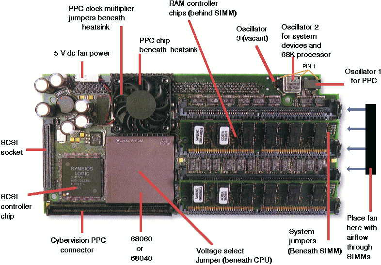
The PPC board can use up to 3 separate clock oscillators to provide timing for the CPUs and system devices. System devices include the onboard SCSI controller, the interface to the CVPPC video card and some Amiga motherboard timing. The clock oscillators can be seen in the photo at the top of the page, numbered 1 to 2. Note that position 3 is empty in this picture. These oscillators come in several forms, and again, in the picture, No 1 is in a plastic case and No 2 is in a metal case. Both types are completely interchangeable, assuming they are of the same frequency. Note that pin 1 on each of these is indicated by a dot or notch on the packaging, and if these oscillators are changed, the new one must be given the same orientation as the old. Pin 1 is to the top right in the picture.
PPC clock.
The first clock signal is used to clock the PPC chip, and is not used on the MK III board. This is generated by oscillator No 1, to the right in the picture. Normally it is a 66.666MHz oscillator, which is multiplied by 3 to give 200MHz. In the case of the 233MHz PPC, it is multiplied by 3.5 to give 233MHz. This multiplication ratio can be changed by a set of jumpers (see below). To overclock the PPC chip, you can either change the oscillator or change the multiplier ratio. For a 200MHz PPC, I found a 75MHz oscillator to work best, giving a resultant PPC speed of 225MHz. Otherwise, the original 66MHz oscillator can be retained and the multiplier ratio increased from 3X to 3.5X, giving a PPC speed of 233MHz. Of the two methods, changing the oscillator gave the best overall results. This is because the RAM access is also sped up. Changing the multiplier only speeds up part of the PPC chip itself, and the only times you gain more performance over the oscillator swap method is when the program being executed can fit entirely within the PPC's cache. So if you like running lots of MPEGs, change the oscillator. If you like running small programs like benchmarks, change the jumper. When overclocking, do not use anything higher than 75MHz or increase the multiplier by more than one step. Also do not do both together. It won't work!
System clocks.
The other two clock signals are usually generated together in a single oscillator. For clarity, I'll describe them separately. The system devices are driven from oscillator No 2, which is in the centre. This is a 50MHz oscillator, and its signal is divided by 2 to derive 25MHz clocks for the SCSI controller and for the Amiga motherboard. The modified PCI interface for the CVPPC also gets its timing from this clock. After much experimentation, I found a maximum value of 60MHz to be the best, giving a worthwhile speedup to the interface for the CVPPC while still maintaining full reliability for SCSI and motherboard devices. Benchmark values for the CVPPC can be found below. The CVPPC itself can also be overclocked.
68060 clock.
The third clock signal is used to drive the 68060 (or 68040). Normally it is also derived from oscillator No 2 in the centre, however, by changing jumpers (see below) it is possible to assign this to the 3rd oscillator position on the left. By then fitting an appropriate oscillator, the user can then overclock the CPU separately from the SCSI and motherboard interface. This means that the 68060 can be overclocked further than the 60MHz allowed by oscillator No 2. I have tested both 50MHz and 60MHz Rev 1 68060s, (Mask 1F43G, see below) as well as Rev 6 (mask 71E41J). The 50MHz Rev 1 version gave a maximum of 65MHz and the 60MHz Rev 1 gave a maximum of 67MHz. The 50 Mhz Rev 6 almost managed 80 MHz (it was slightly flaky). However, switching the memory to 70ns cleared that up. I would expect that using 50 ns RAM may also cure this problem, as the amount of flakiness varied with different memory installed (all my memory is rated at 60 ns). Trying a Rev 6 in a later (233 MHz) CSPPC gave reliable operation at 80 MHz, even with the RAM set to 60 ns. There is also another problem if the 060 is clocked using the 3rd oscillator in an early version board. Some PPC programs will hang after running a while (eg ISIS PPC or Frogger). This will limit you to overclocking with the centre oscillator only, unless a switch is provided to switch oscillators for the times when these particular programs are used (see below). You then have the choice of 55-60MHz for reliability or 66-80MHz for speed.
68060 versions.
The 68060 is available in a number of different ‘Mask’ versions. These are similar to the processor ‘steppings’ as found in the Intel x86 processors. Later mask versions are made using more advanced techniques, giving smaller die sizes which generate less heat in operation compared to the earlier masks. They are much more suitable for overclocking than the earlier masks.
Unfortunately, these later mask versions are very much in demand, especially Rev 6 (71E41J). Unless you can confirm the provenance of the 68060 you are buying, especially from some Chinese sellers on certain mainstream sites, you will almost certainly get a counterfeit chip. These have had the old markings removed and new ones added by either the seller, or their supplier(s). At best you may find you now actually have a Rev 1 68060. At worst you may have a completely different or faulty chip masquerading as your shiny new rev 6 68060. The only 100% reliable way to confirm you have a genuine 68060 is to install it in an Amiga and run 'WhichAmiga' from Aminet. This will give you the revision number, which is stored internally in the chip and cannot be changed. If you can't test the chip this way before purchase, look at the surface of the chip. If it has scratches, marks and/or residue from heatsink compound, then it is less likely to be counterfeit as the process of remarking usually results in these marks being removed or covered over. Note that this counterfeit chip problem is not confined to the 68060. It is also common with other vintage chips that are in high demand.
Below is a table of some common 68060 mask versions, with suggested CSPPC/MK III overclock frequencies.
| Part No. | Mask | Rev | Feature size | Default | Overclock | Note |
|---|---|---|---|---|---|---|
| XC68060RC50 | 01F43G | 1 | 0.6 um | 50 Mhz | 60 MHz | I got 65 MHz with mine. |
| XC68EC060RC60 | 01F43G | 1 | 0.6 um | 60 MHz | 66 MHz | I got 67 MHz. Has functional FPU. Probably a standard 50 MHz part, factory selected for ability to run at 60 MHz. |
| XC68060RC50 | 1G65V | ? | 0.6 um | 50 MHz | 60 MHz | Some bugfixes applied. |
| XC68EC060RC50 | 2G59Y | 4 | 0.42 um | 50 MHz | N/A | All bugs removed, die shrunk, this mask is for EC & LC versions. |
| XC68060RC50 | 0E41J | 4 | 0.42 um | 50 MHz | 80 MHz est max | All bugs removed, die shrunk, this mask is for full 68060. |
| MC68EC060RC50 | 3G59Y | 5 | 0.42 um | 50 MHz | N/A | Improved metalisation, this mask is for EC & LC versions. |
| XC68060RC50 | 1E41J | 5 | 0.42 um | 50 MHz | 80 MHz est max | Improved metalisation, this mask is for full 68060. |
| MC68060RC50 | 71E41J | 6 | 0.32 um | 50 MHz | 80 MHz | Limited by CSPPC board version, cooling, and memory. There are reports this mask will go as high as 133 MHz. | MC68EC060RC75 | 71E41J | 6 | 0.32 um | 75 MHz | N/A | EC & LC versions, probably can go to 133 MHz. |
Cooling.
This board runs quite hot even at standard speeds, and so will require extra attention to cooling when overclocked. You will need to perform the following modifications in order to help keep the board cool. Fit a heatsink to the 68060. I used a "bed of nails" heatsink taken from an old A3640 board. It works very well. The Permedia 2 chip (if you have a CVPPC) will also now need a heatsink. I used a small self adhesive PC 'chipset' heatsink on top of this chip. If you can't find the correct type of heatsink glue, you could use superglue, though it may weaken from the heat after a while. The PPC CPU does not need any extra cooling, though make sure its heatsink and fan are working OK. Finally add a fan and position it as shown in the picture above so that it blows air down along the memory SIMMs and across the board. This keeps the CPLD chips under those SIMMs cool (they tend to run very hot, even when not overclocked). The addition of this fan also helps to keep cool air circulating across the entire board. If you have a desktop case which lacks the required room, look here for details on how to fit this fan. Also I recommend doing the other mods outlined there to improve cooling further. Even with extra cooling, I strongly advise adding the 'turbo' switch mentioned below. By using this, you can run your board with a modest amount of overclocking eg: 55MHz for everyday use. Use of the higher speed should be limited to those times when you only really need it.
Jumper Settings:
There are three different sections utilising jumpers. They are PPC division ratio, found under the PPC heatsink; general system timing, found on the edge of the PCB, near the SIMMs; and the 68K voltage selector, found inside the 68K socket (remove the 68K chip to reveal it). Be VERY CAREFUL when changing these jumpers. They are TINY surface mount jumpers, which look like surface mount resistors, and both the jumpers and the PCB tracks can be very easily damaged. Get a qualified electronics technician to change them. Note that they are completely unlike the standard pin type jumpers which use removable shorting blocks.
PPC clock multiplier jumpers.
These jumpers are located beneath the PPC chip's heatsink, which is attached to the PCB by two spring clips. With the PCB oriented as in the picture at the top of the page, the jumpers are located to the top left of the PPC chip. Refer to the diagram below for the various multiplier ratios. For example, the leftmost one below is the default setting for a 200MHz PPC board, using a 66.666MHz oscillator in position 1. This is multiplied by 3 to give 200MHz. Changing the positions of the jumpers to reflect 3.5:1 will multiply the 66.666MHz clock by 3.5, giving a frequency of 233MHz.
System jumpers.
These jumpers are located to the right of the PCB, underneath the second from top SIMM. Below is a table of what they may do. Note that I obtained these results from experimentation, so I can't promise total accuracy. The jumper positions shown are for a standard 200MHz PPC, 50MHz 060 board. A clearer idea of their location can be found in the picture below, in the "How to overclock" section.
|
1:- Unknown -
this jumper has no apparent effect. |
68K CPU power voltage jumper.
A jumper for selecting the supply voltage for the 68K chip is also provided on the PCB. This can be found by removing the 68K chip. It is located in the hollow centre section of the 68K socket. Like the other jumpers it is a surface mount link, soldered in place. Fortunately it is somewhat larger than the other jumpers, and it also has the settings marked on the PCB. The default position (for an 060 board) is 3.3 volts. The alternate position for an 040 board is 5 volts. Be careful - you must NEVER operate this board with a 68060 installed and the jumper set to 5 volts. You will destroy the 68060! On the other hand operating the board set to 3.3 volts with a 68040 installed will not cause damage....it just won't work.
How to overclock - step by step:
This step by step outline shows you how to overclock a 200 or 233MHz PPC card with 50MHz 060. The oscillator values I have quoted here are suggested values that should work for most people. You may need to experiment with different oscillators if you run into problems. If you only want to overclock the PPC, you only need to do either step 1a or 1b. If you want to overclock the 060 only, or you have a MKIII card, do all steps with the exception of 1a/1b. If you want the simplest possible modification for overclocking the 060, (limited to 60MHz), do step 2 only with or without step 1a/1b. If you have a newer version CSPPC, where it is possible to alter the RAM precharge settings (see above), you may skip step 4 if you wish.
1a: EITHER carefully remove the 66MHz oscillator (number 1) and replace it with a 75MHz oscillator.
1b: OR change the multiplier jumpers as per the illustration above. I advise only increasing it to the next step up. For example, x3 (200MHz) to x3.5 (233MHz).
2: Carefully remove the 50MHz oscillator (number 2) and replace it with a 55-60MHz oscillator.
3: Solder a 66-80MHz oscillator into the empty number 3 position. Users with Rev 6 060s can try faster oscillators - up to 80MHz.
4: Using the utmost care, remove the bottom jumper (No 6) and fit a SPDT type switch, wire the common to the centre solder pad, with the 2 switch contacts going to the other two pads. The "turbo" switch in a standard tower case is ideal for this. You can then select slow (I used 55MHz, though up to 60 should be OK) or high (up to 80MHz, assuming a Rev 6 060 is used) as appropriate. The switch can be operated while the system is powered up. I used a small connector glued to the board, with fine wire-wrap wire running to the pads.
5: Add a heatsink to the 060.
6: Add a heatsink to the Permedia video chip (if you have a CVPPC card).
7: Add a fan positioned to blow air down between the SIMMs (particularly between the top and second SIMM). Refer to the picture at the top of this page.
8: Test thoroughly, over several hours of continuous use.
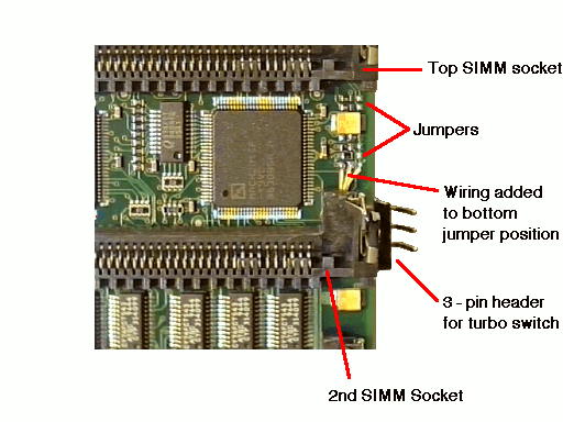
Note the position of the system jumpers, on the right-hand side of the PCB.
PPC Benchmark results.
I did a few tests to see how effective the overclocking was. You can clearly see the effects of faster RAM access for the PPC, as well as overclocking of the CVPPC data bus. The tests, from left to right are: PPC heatsink temperature, taken with an ambient temperature of 20 deg C, RC5 benchmark, taken with the old PPC RC5 client in benchmark mode (note that there is now a new, faster RC5 client), and ISIS PPC, running an MPEG called "Mandtrip" which can be found on Aminet. There were no "hacks" running in the system during these tests. 060 results can be found in the various SysSpeed modules below. The top (200Mhz) line is the results before overclocking.
Multiplier=66x3 (200MHz):- Temp=47.5 deg C, RC5=648334 Kkey/sec, ISIS=53.76fps.
Multiplier=75x3 (225MHz):- Temp=48.9 deg C, RC5=729222 Kkey/sec, ISIS=57.53fps.
Multiplier=66x3.5 (233MHz):- Temp=50.0 deg C, RC5=755788 Kkey/sec, ISIS=56.69fps.
Results with System clock=60MHz (overclocked CVPPC interface)
Multiplier=66x3 (200MHz):- Temp=47.4 deg C, RC5=648357 Kkey/sec, ISIS=58.26fps.
Multiplier=75x3 (225MHz):- Temp=48.9 deg C, RC5=729228 Kkey/sec, ISIS=63.53fps.
Multiplier=66x3.5 (233MHz):- Temp=50.3 deg C, Rc5=754287 Kkey/sec, ISIS=61.91fps.
Upgrading an 040 to an 060:
Both the Cyberstorm PPC and the Cyberstorm MKIII boards allow the use of either a 68060 or a 68040 processor. Both processors are quite similar, with the exception that the 68060 runs on 3.3 volts instead of the 68040's 5 volts, and the 68040 uses a 2x clock signal instead of the 68060's 1x clock. The following outline shows how to upgrade a 25MHz 68040 board to a 50MHz 68060. Note that I have not actually tried this myself - I do not have an 040 chip!
1: Install the appropriate 68060 libraries. Copy both the 68060.library and the 68040dummy.library into SYS:LIBS. Delete (or remove) the existing 68040.library, then rename the 68040dummy.library to 68040.library. When finished, power down the Amiga. You can disregard this step if using OS 3.2.2.1, as you can install the appropriate libraries as required.
2: Carefully remove the 68040 chip by gently levering it up with a small screwdriver. Avoid bending the pins.
3: Locate the voltage select jumper, in the centre of the 68040 socket. Move it to the 3.3 volt position by careful soldering. (see above).
4: Move Jumper No 5 (see above) to the 68060 default position.
5: Install the 68060 chip into the socket.
Problems and solutions:
* Do not use crystal sockets, as socket and oscillator will be too tall and will foul the top-most SIMM. I suggest using sockets during the testing process, with only 2 SIMMS fitted - then when you are happy with the overclocking, remove the sockets and solder the oscillators in. Otherwise you could try mounting the sockets remotely, but be careful to avoid long leads.
* Do not use tall oscillators for the same reason given above.
* Pay attention to correct oscillator orientation. Getting it wrong will destroy the oscillator.
* Be very careful when removing the old oscillators, as some people have damaged the copper tracks on their board.
* If using sockets for testing, use quality machined pin types (with round pins) to avoid damaging the PCB.
* You will need a small fan blowing through the SIMMs to ensure effective cooling, ie one taken from a CPU cooler is sufficient.
* Make sure the 200 pin CPU connector to the motherboard is clean and in good condition and that the CSPPC is screwed in place (see text)
* Make sure you have good quality 60nS SIMMS and that their contacts are clean. Even better if you can find 50 ns RAM. Many CSPPC problems are caused by bad memory.
* Make sure you have the latest Flash ROM revision to ensure best SCSI reliability.
* Check your power supply and power wiring if you have unexplained crashes. Check for overheating contacts in the 5V DC supply, especially on the 6-pin connector between the power supply and the motherboard.
* Some PPC programs crash when the 060 is clocked separately to the system devices. I suggest using the "turbo" switch (outlined above) and have the 060 running at 60MHz while running these programs. This problem does not happen if you have a recent version CSPPC.
* If you have SCSI lockups, make sure that the decimal value of maxtransfer if divided by your blocksize gives an integer result. For example, if you are using the default value of 512 bytes for your blocksize, your maxtransfer value should be 0xfff000. Set this for all hard drives and partitions on your CSPPC SCSI controller. Note that these SCSI lockups can often freeze your entire system, with the SCSI light permanently on.
* If you have a 233Mhz PPC (or have overclocked to that frequency) there is a bug in the PPC chip, which can be patched with csppc233fix.lha from Aminet.
Introduced 11th July 1998. Updated 17 July 2024. Version 6.1