1571 drive substitution.
The Newtronix D502 drive mechanism as used in the 1571 and C128DCR is notorious for having open circuit heads. Replacements for these are unobtanium, and it is impossible to repair them, so any way of getting these drives to work is most welcome. I was recently in the situation of having a 1571 with bad heads, and a C128DCR with a missing drive. I decided to try modifying a different drive to use in the C128DCR. These modifications should be the same if you are installing a new drive in a 1571.
I used a Chinon FZ502, as I had two of these, one of them was NOS. The modification mostly entails removing the wires and connectors from the old Newtronix drive and adding them to the new Chinon drive in the appropriate places.
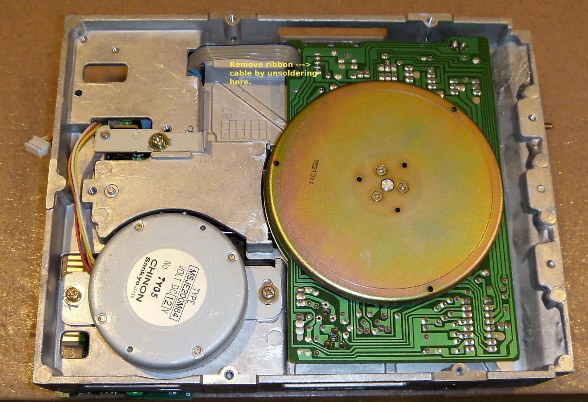
Start by disconnecting and removing the interface board from the new drive. Keep it as it will be needed later.
Stepper motor.
On the new floppy drive, cut the existing plug off the five stepper motor wires.
On the old floppy drive, cut the six wires to the stepper motor, leaving sufficient length of wires attached to CN15, so that when joined to the new stepper motor, they will reach the motherboard connector.
Join the wires as below:
CN15 pins 1&2 (red): Join together and connect both to the white wire on the new motor.
CN15 pin 3 (yellow): Connect to Red wire on new motor.
CN15 pin 4 (orange): Connect to Yellow wire on new motor.
CN15 pin 5 (black): Connect to Orange wire on new motor.
CN15 pin 6 (brown): Connect to Brown wire on new motor.
Spindle motor.
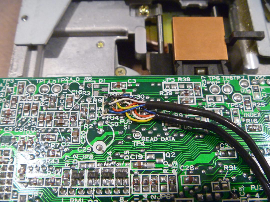
Remove the grey 4-way ribbon cable on the motor PCB from the new drive. Note that the wire with the blue stripe corresponds to pin 1, the other wires are in sequence. Click on the images for a larger view.
Remove the 3 wires leading to CN17 from the motor PCB on the old drive. Make sure they are long enough to reach from CN17 to the appropriate places on the new PCB.
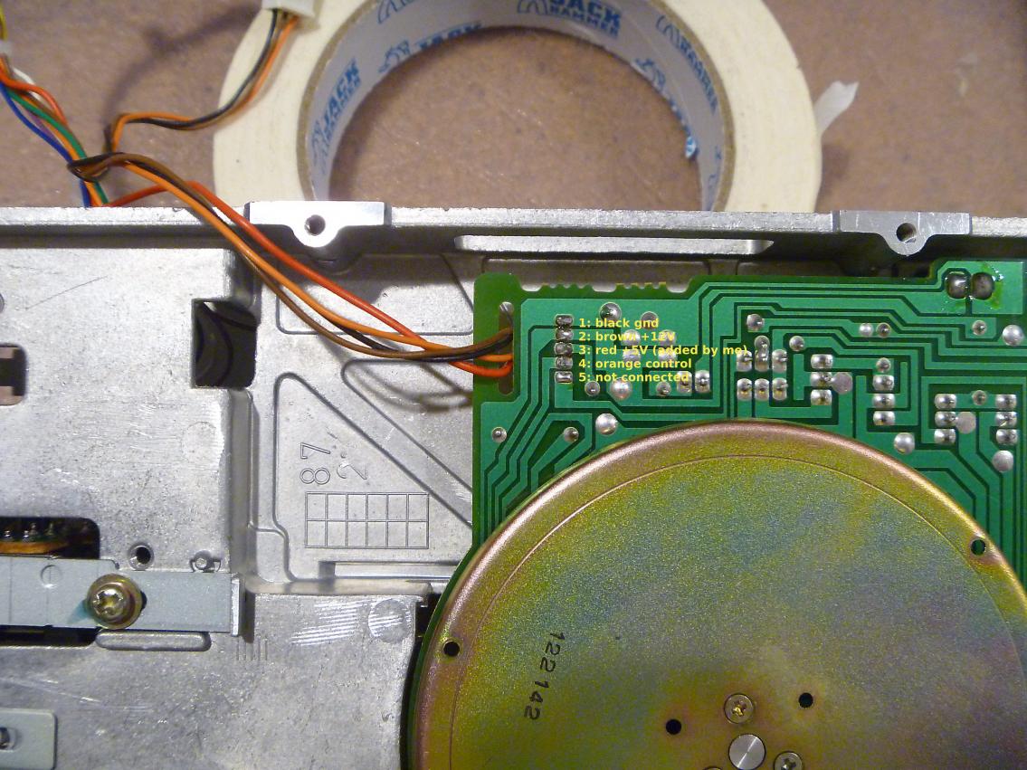
Solder these wires to the new PCB as listed below:
CN17 pin 1 (black) to the 1st PCB pad, which previously had the wire with the blue stripe.
CN17 pin 2 (brown) to the 2nd PCB pad.
CN17 pin 3 (orange) to the 4th PCB pad (skip pad #3)
The new PCB requires +5V, which was not supplied to the old PCB. This can be obtained from the motherboard. In my case I used pin 6 on CN14, by adding a pin and wire to the previously vacant spot on the connector and soldering it to pad #3 on the motor PCB.
Track 0 sensor.
While both drives use exactly the same track 0 sensor, they were wired in reverse to each other on different PCBs, so you will need to replace the sensor assembly from the new drive with the one taken from the old drive. Disconnect CN14 from the old drive. Make sure the wires from CN14 are long enough to reach the appropriate places on the new drive when CN14 is plugged into the motherboard.
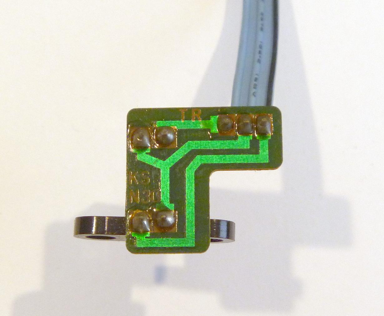
Track 0 sensor removed from new drive:
Track 0 sensor from old drive, shown installed in new drive:
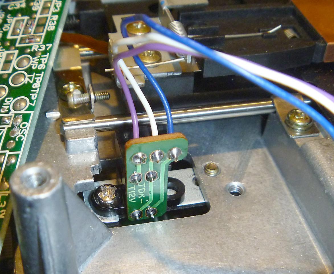
Check to make sure the sensor is wired as shown in the above picture, and as listed below:
CN14 pin 8 (purple) to LED anode
CN14 pin 9 (white) common (LED cathode & sensor)
CN14 pin 10 (blue) sensor
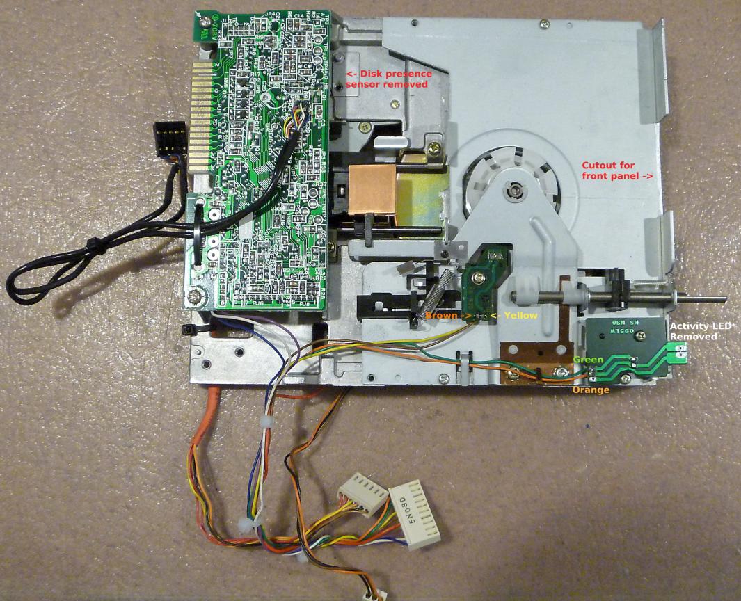
Index & write protect sensors.
Remove original ribbon type wires and replace with wires from CN14 as shown below. Also remove the drive activity LED. This should be self explanatory, but also note the disk presence sensor and its associated wiring on the new drive is not used and needs to be removed as shown. Also note the gap cut into the flange on the metal plate at the front of the drive to avoid fouling the plastic drive fascia.
Heads.
The interface board from the new drive contains two special connectors for the small ribbon cables for the heads. These need to be isolated from the rest of the (now redundant) circuitry on the PCB. This can be achieved by cutting the tracks to the terminals, or by removing two components, which was the method I chose.
Remove D1, on the solder side, next to the two terminals.
Remove the Sony CX20185 IC from the component side of the PCB.
I also removed the Molex power connector to provide a clear place to provide strain relief for the new head leads by using a cable tie. This can be seen in the picture above.
Connect the head leads taken from the old drive as shown below:
Noting the pin numbers printed on the PCB, attach the leads as shown below to PJ4 and PJ5. Be aware the PJ4 & PJ5 terminals are mounted 180 deg from each other.
1: blue
2: red
3: white
4: yellow
5: black.
The wires from PJ4 go to the even numbered pins on the motherboard connector (on the top) and PJ5 goes to the odd numbered pins (on the bottom). Reattach the head ribbon cables into the two sockets on the underside of the interface board and reinstall the board back into its original location.
Final notes.
As previously mentioned, the front flange will need to be cut away to prevent fouling of the rear of the front fascia. The drive latch is in a different position, requiring the existing hole on the front fascia to be filled and a new one drilled. To achieve this, I glued a small piece of ABS plastic behind the hole (a piece cut from a drive blanking plate works well). The hole was then filled with a kneadable epoxy putty and then sanded smooth. The front panel was then painted. In my case, the front panel had been very badly hacked by a previous owner, and I had several other holes that had to be filled anyway.
The drive is a very tight fit in the bay in my C128DCR. I had to slightly file away the raised areas on the sides of the drive where the mounting holes are. Fortunately the metal is very soft.
As I had to remove and replace the track 0 sensor, I had to do a full alignment of the drive, including track 0 sensor position. I understand the early model 1541s also used the same mechanism as the 1571, though with only one head. These seem to have exactly the same problems with bad heads. While I don't have any of those older 1541s, I would expect that this drive would work just as well in a 1541. Of course the upper head would not be used.
Back to main Amiga page.
Introduced 21st May 2023. Version 1.0